
Calibrating device for tracing aiming point of typoscope telescope

A calibration method and technology for vision aids, which are applied to instruments, optical components, optics, etc., can solve the problems of error-prone, cumbersome calibration points, and difficult calibration process, and achieve the effect of a simple calibration method.

Inactive Publication Date: 2011-09-07
DALIAN MARITIME UNIVERSITY
View PDF0 Cites 0 Cited by
  • Summary
  • Abstract
  • Description
  • Claims
  • Application Information

AI Technical Summary

Problems solved by technology

However, if there are many calibration points, it will be cumbersome and error-prone to accurately locate each calibration point
Especially for low-vision drivers, such as those in the low-vision driving behavior study, who have poor vision, it will be very difficult for them to complete this tedious calibration process
Of course the number of calibration points can be reduced by increasing the number of cameras and IR light sources, but this will increase the cost and complexity of the system

Method used


Image

  • Calibrating device for tracing aiming point of typoscope telescope
  • Calibrating device for tracing aiming point of typoscope telescope
  • Calibrating device for tracing aiming point of typoscope telescope

Examples


Embodiment Construction

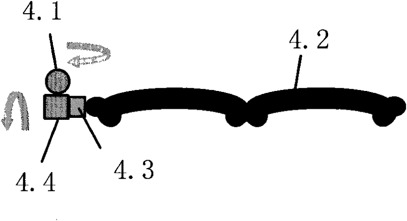
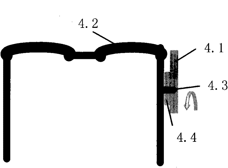
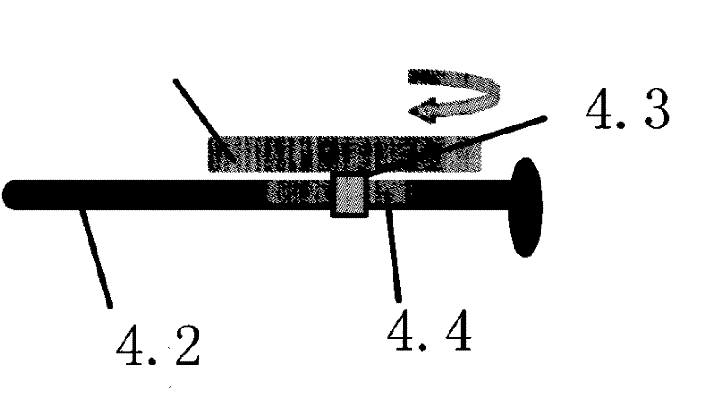
[0027] Specific embodiments of the present invention are as attached Figure 1-3 As shown, the calibrator 4 is composed of a laser transmitter 4.1, a calibrator bracket 4.2, a connector 4.3, and a laser transmitter fixing bracket 4.4. Connect the laser transmitter fixing bracket 4.4 to the calibrator bracket 4.2 through the connecting piece 4.3. And it can rotate horizontally with the link 4.3 as the axis, and drive the laser emitter 4.1 to rotate, so that the laser point projected by the laser emitter 4.1 can move in the vertical direction. The laser emitter 4.1 is fixed on the link, so that the laser point projected by the laser emitter 4.1 can move in the horizontal direction. Laser emitter 4.1 among the present invention is to adopt laser pointer. The calibrator 4 can be freely disassembled on the calibrator bracket 4.2.

[0028] Working principle of the present invention:

[0029]1. The reflection of the windshield glass on the laser point in the present invention wil...


PUM


Abstract

The present invention relates to a calibrating method for tracing an aiming point of a typoscope telescope, which is used for calibrating and tracing the aiming point of the telescope by a driver wearing a typoscope in a behavior state of driving. A calibrator is additionally installed on the typoscope provided with the telescope, and the calibrator comprises a laser transmitter, a calibrator bracket, a connecting element and a laser transmitter fixing bracket, wherein the laser transmitter is installed on the laser transmitter fixing bracket, and three infrared reflecting labels are stuck in the front of a spectacle frame of the typoscope and form a triangular geometrical shape. The movement direction of the typoscope telescope is traced by the infrared reflecting labels, and a calibrating point is positioned by the laser transmitter. The calibrating method is irrelevant to the low-vision driver, and the calibrating process applied to the driving environment is finished by an operator instead of the driver. The invention has the characteristics of convenient use, advanced performance, precise calibration, wide application range, simple structure, and the like.

Description

Technical field [0001] The invention relates to a method for calibrating aiming point tracking of a telescope for a vision aid, in particular to a method for calibrating the aiming point tracking of a telescope for a driver wearing a vision aid in a driving behavior state. Background technique [0002] As people live longer, so does the number of people with age-related low vision. According to the 2000 U.S. Census, an estimated 2.4 million U.S. adults had low vision (corrected best vision of less than 20 / 40). Many people lose the opportunity to drive because they cannot meet vision requirements, impacting quality of life. Vision aids have been used since the 1950s, namely vision aids that fix binoculars on glasses, and began to be used for driving in the 1960s. Using the magnification provided by the vision aid telescope can compensate for the loss of vision; currently, 39 states in the United States allow people with low vision to drive with this vision aid. Most of the...

Claims


Application Information

Patent Timeline
Patent Type & Authority Patents(China)
IPC IPC(8): G02B27/01
Inventor 付先平
Owner DALIAN MARITIME UNIVERSITY
Features
  • Generate Ideas
  • Intellectual Property
  • Life Sciences
  • Materials
  • Tech Scout
  • Unparalleled Data Quality
  • Higher Quality Content
  • 60% Fewer Hallucinations
Learn More