Halbach array external rotor of composite-structure permanent magnet motor

A composite structure and permanent magnet motor technology, applied in the field of Halbach array outer rotor, can solve the problems of inflexible selection of motor poles and magnetic coupling of composite structure motors, and achieve the effect of reducing iron loss and improving motor efficiency

Inactive Publication Date: 2010-05-12
HARBIN INST OF TECH
View PDF2 Cites 28 Cited by
  • Summary
  • Abstract
  • Description
  • Claims
  • Application Information

AI Technical Summary

Problems solved by technology

[0005] In order to solve the magnetic coupling problem of the composite structure motor and the inflexible selection of the numb

Method used


Image

  • Halbach array external rotor of composite-structure permanent magnet motor
  • Halbach array external rotor of composite-structure permanent magnet motor
  • Halbach array external rotor of composite-structure permanent magnet motor

Examples


specific Embodiment approach 1

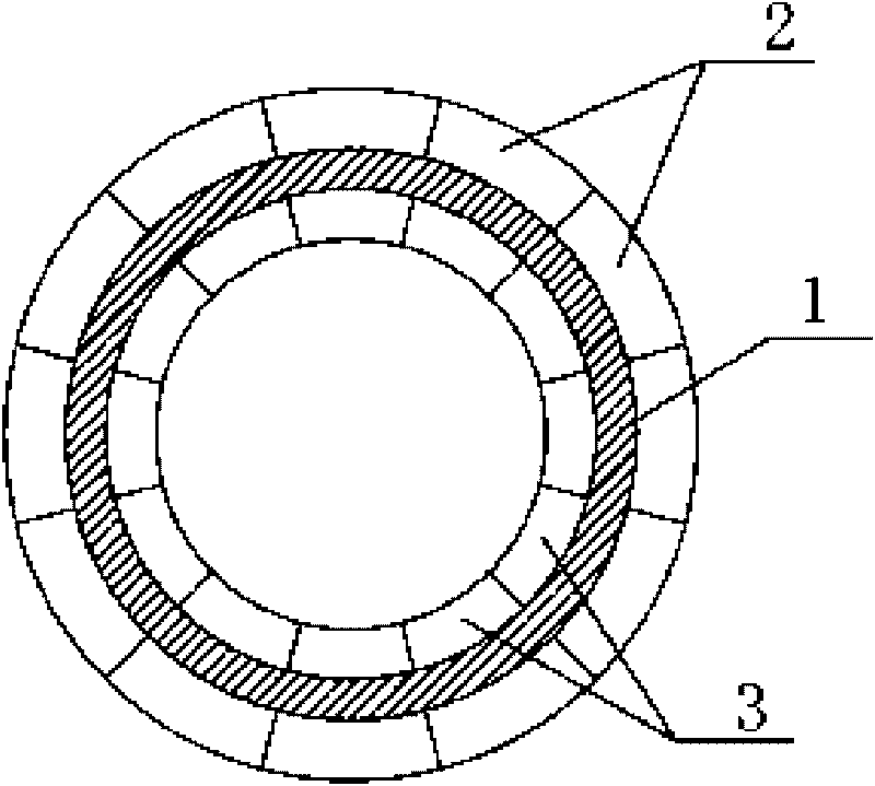
[0009] Specific implementation mode one: combine Figure 1 to Figure 7 Describe this embodiment, this embodiment is made up of rotor core 1, outer layer Halbach permanent magnet array 2 and inner layer Halbach permanent magnet array 3; Rotor core 1 is a cylindrical iron core, outer layer Halbach permanent magnet array 2 and inner layer Halbach permanent magnet array Each permanent magnet in the permanent magnet array 3 is a tile-shaped permanent magnet, and the tile-shaped permanent magnets of the outer layer Halbach array permanent magnet 2 are evenly arranged on the outside of the rotor core 1 along the circumferential direction, and the outer layer Halbach array permanent magnet 2 The inner surface of the weakened side of the tile-shaped permanent magnet is fixedly connected to the outer surface of the rotor core 1. When the outer layer Halbach array permanent magnet 2 is fixed, the side where the magnetic field is strengthened is away from the rotor core 1, and the inner la...

specific Embodiment approach 2

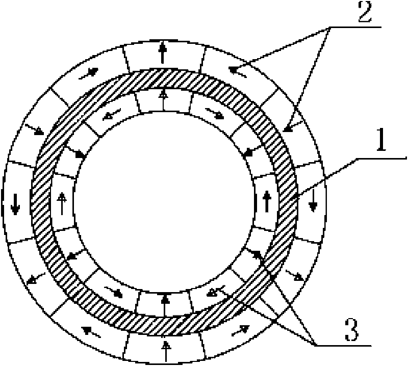
[0010] Specific implementation mode two: combination figure 2 , image 3 , Figure 4 , Figure 8 , Figure 9 and Figure 10 Describe this embodiment, the difference between this embodiment and the specific embodiment is that the outer layer Halbach permanent magnet array 2 and the inner layer Halbach permanent magnet array 3 adopt the same form of Halbach permanent magnet array, and the outer layer Halbach permanent magnet array 2 and the inner layer Halbach permanent magnet array Layer 3 Halbach permanent magnet array 3 adopts two 90° magnetized Halbach permanent magnet arrays per pole, three 60° magnetized Halbach permanent magnet arrays per pole or four 45° magnetized Halbach permanent magnet arrays per pole A type of magnet array. Other compositions and connection methods are the same as those in Embodiment 1. The more the number of permanent magnets per pole, the less the magnetic flux between the two layers of Halbach arrays.

specific Embodiment approach 3

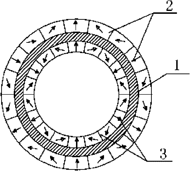
[0011] Specific implementation mode three: combination Figure 5 to Figure 7 Illustrate this embodiment, the difference between this embodiment and the specific embodiment is that the outer layer Halbach permanent magnet array 2 and the inner layer Halbach permanent magnet array 3 adopt Halbach permanent magnet arrays of different forms, and the outer layer Halbach permanent magnet array 2 and the inner layer Halbach permanent magnet array The layer 3 Halbach permanent magnet array adopts two 90° magnetized Halbach permanent magnet arrays per pole, three 60° magnetized Halbach permanent magnet arrays per pole, or four 45° magnetized Halbach permanent magnet arrays per pole. A type of magnet array. Other compositions and connection methods are the same as those in Embodiment 1.


PUM


Abstract

The invention discloses a Halbach array external rotor of a composite-structure permanent magnet motor, relating to an external rotor of a composite-structure permanent magnet synchronous motor and solving the problems of magnetic coupling and flexible selection of pole numbers of a composite-structure motor. A rotor core of the external rotor is of a cylindrical iron core, all permanent magnets in the outer layer and the inner layer of Halbach permanent magnet array are tile-shape permanent magnets which are evenly distributed inside and outside the rotor core in the circumferential direction, and the inner surfaces of one sides of the tile-shaped permanent magnets with weakened magnetic field in the outer layer Halbach permanent magnet array and the outer surfaces of one sides of the tile-shaped permanent magnets with weakened magnetic field in the inner layer Halbach permanent magnet array are respectively and fixedly connected with the outer surface and the inner surface of the rotor core. Magnetic flux in the rotor core is extremely less whether pole numbers are equal or not, so that independent control can be realized, a whole hybrid power system is in coordinated operation, and motors combined together can flexibly select magnetic pole numbers as required by actual power grade and base speed.

Description

technical field [0001] The invention relates to a permanent magnet synchronous motor rotor, in particular to a Halbach array outer rotor of a composite structure permanent magnet motor. Background technique [0002] Fuel consumption and exhaust emission pollution of traditional internal combustion engine vehicles are hot issues of worldwide concern. In order to overcome the problems of low efficiency and serious emissions caused by the single drive of the internal combustion engine system in existing vehicles, various motors, batteries and power converters are introduced into the vehicle drive system to work in harmony with the traditional internal combustion engine to achieve energy saving and emission reduction for vehicles . [0003] The motor involved in the international patent with the patent number PCT / NL03 / 00155, the publication number WO03075437, and the publication date on September 12, 2003, and the Chinese patent with the patent number 200510130739.5, the public...

Claims


Application Information

Patent Timeline
IPC IPC(8): H02K1/27
Inventor 郑萍赵静佟诚德白金刚柯文静
Owner HARBIN INST OF TECH
Why Eureka
Try Eureka