Halbach array disk rotor of permanent magnet motor with composite structure

A technology of permanent magnet motor and composite structure, applied in the field of Halbach array disc rotor, can solve problems such as motor magnetic coupling

Inactive Publication Date: 2010-05-12
HARBIN INST OF TECH
View PDF1 Cites 13 Cited by
  • Summary
  • Abstract
  • Description
  • Claims
  • Application Information

AI Technical Summary

Problems solved by technology

[0004] In order to solve the magnetic coupling problem of the composite structure motor and the flexible selection of the numb

Method used


Image

  • Halbach array disk rotor of permanent magnet motor with composite structure
  • Halbach array disk rotor of permanent magnet motor with composite structure
  • Halbach array disk rotor of permanent magnet motor with composite structure

Examples


specific Embodiment approach 1

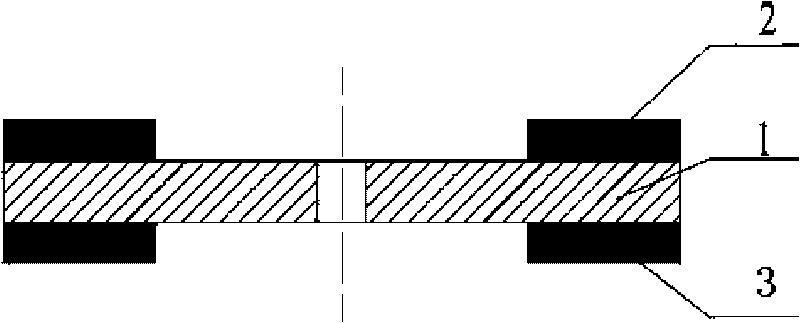
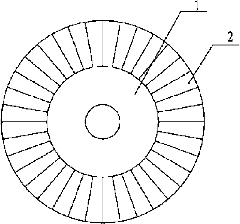
[0008] Specific implementation mode one: combine figure 1 with figure 2 Describe this embodiment, this embodiment is made up of disc rotor iron core 1 and two groups of Halbach permanent magnet arrays; The surfaces of the Halbach permanent magnet array 2 and another group of Halbach permanent magnet arrays 3 on the side where the magnetic field is weakened are respectively fixed on the two surfaces of the disc rotor core 1. When each group of Halbach permanent magnet arrays is fixed, the side where the magnetic field is strengthened is away from the disk. Each permanent magnet in each set of Halbach permanent magnet arrays is a sector-shaped permanent magnet, and the sector-shaped permanent magnets in each set of Halbach permanent magnet arrays are evenly arranged radially around the axis of the disc-type rotor core 1. Two groups of Halbach permanent magnet arrays 2 respectively provide axial main magnetic flux for the two motors.

specific Embodiment approach 2

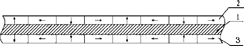
[0009] Specific implementation mode two: combination image 3 , Figure 4 , Figure 5 , Figure 9 , Figure 10 with Figure 11 Illustrate this embodiment, the difference between this embodiment and the specific embodiment is that one group of Halbach permanent magnet array 2 and another group of Halbach permanent magnet array 3 adopt the Halbach permanent magnet array of the same form, and one group of Halbach permanent magnet array 2 and Another set of Halbach permanent magnet arrays 3 simultaneously adopts a 90° magnetized Halbach permanent magnet array with two pieces per pole, a 60° magnetized Halbach permanent magnet array with three pieces per pole, or a 45° magnetized Halbach permanent magnet array with four pieces per pole One of the Halbach permanent magnet arrays, one set of Halbach permanent magnet arrays 2 and another set of Halbach permanent magnet arrays 3 have the same or different pole numbers. Other compositions and connection methods are the same as thos...

specific Embodiment approach 3

[0010] Specific implementation mode three: combination Image 6 , Figure 7 with Figure 8 Illustrate this embodiment, the difference between this embodiment and the specific embodiment is that one group of Halbach permanent magnet arrays 2 and another group of Halbach permanent magnet arrays 3 adopt Halbach permanent magnet arrays of different forms, and one group of Halbach permanent magnet arrays 2 and Another group of Halbach permanent magnet arrays 3 adopts the 90° magnetized Halbach permanent magnet array of two pieces per pole, the 60° magnetized Halbach permanent magnet array of three pieces per pole, or the 45° magnetized Halbach permanent magnet array of four pieces per pole. One of the Halbach permanent magnet arrays, one set of Halbach permanent magnet arrays 2 and another set of Halbach permanent magnet arrays 3 have the same or different pole numbers. Other compositions and connection methods are the same as those in Embodiment 1.


PUM


Abstract

The invention relates to a Halbach array disk rotor of a permanent magnet motor with a composite structure, relating to a motor of a permanent magnet synchronous motor, and solving the problem of magnetic coupling of motors with composite structures and the problem that the number of magnetic poles can be freely selected. The Halbach array disk rotor consists of a disk rotor core and two sets of Halbach permanent magnet arrays, the surfaces of the magnetic field weakening sides of the Halbach permanent magnet arrays are respectively fixed on the two surfaces of the disk rotor core 1, each permanent magnet in each Halbach permanent magnet array is in a fan shape, and the fan-shaped permanent magnets in each Halbach permanent magnet array are arranged around the shaft axis of the disk rotor core in a radial form. Whether the numbers of the poles of the two Halbach permanent magnet arrays are the same or not, magnetic flux poles in the rotor core are extremely less, the rotor core is rather unsaturated, magnet-circuits of the two motors can not be coupled, the two rotors can be controlled independently, the integral hybrid system can run more harmoniously, and each of the rotor can flexibly select the number of the magnetic poles according to power level and basic rate that are actually needed.

Description

technical field [0001] The invention relates to a permanent magnet synchronous motor rotor, in particular to a Halbach array disc rotor of a composite structure permanent magnet synchronous motor. Background technique [0002] Fuel consumption and exhaust emission pollution of traditional internal combustion engine vehicles are hot issues of worldwide concern. In order to overcome the problems of low efficiency and serious emissions caused by the single drive of the internal combustion engine system in existing vehicles, various motors, batteries and power converters are introduced into the vehicle drive system to work in harmony with the traditional internal combustion engine to achieve energy saving and emission reduction for vehicles . Patent No. CN200610010472.0, Publication No. CN1929243A, Publication Date: March 14, 2007 The composite structure motor involved in the Chinese patent is proposed to solve this problem and applied to the motor of hybrid electric vehicles, ...

Claims


Application Information

Patent Timeline
IPC IPC(8): H02K1/27
Inventor 郑萍赵静佟诚德师巍黄永恒
Owner HARBIN INST OF TECH
Why Eureka
Try Eureka