
Layout method and circuit board

A layout method and circuit board technology, which is applied to printed circuit components, electrical connection printed components, etc., can solve problems such as inability to complete winding, and achieve the effects of proper space, reduced range, and expanded heat dissipation area

Active Publication Date: 2010-05-12
AU OPTRONICS CORP
View PDF0 Cites 0 Cited by
  • Summary
  • Abstract
  • Description
  • Claims
  • Application Information

AI Technical Summary

Problems solved by technology

But today, the number of pins of the driver chip is increasing day by day, this design will inevitably make it impossible to complete the winding in the limited area of ​​the circuit board 600

Method used


Image

  • Layout method and circuit board
  • Layout method and circuit board
  • Layout method and circuit board

Examples


Embodiment Construction

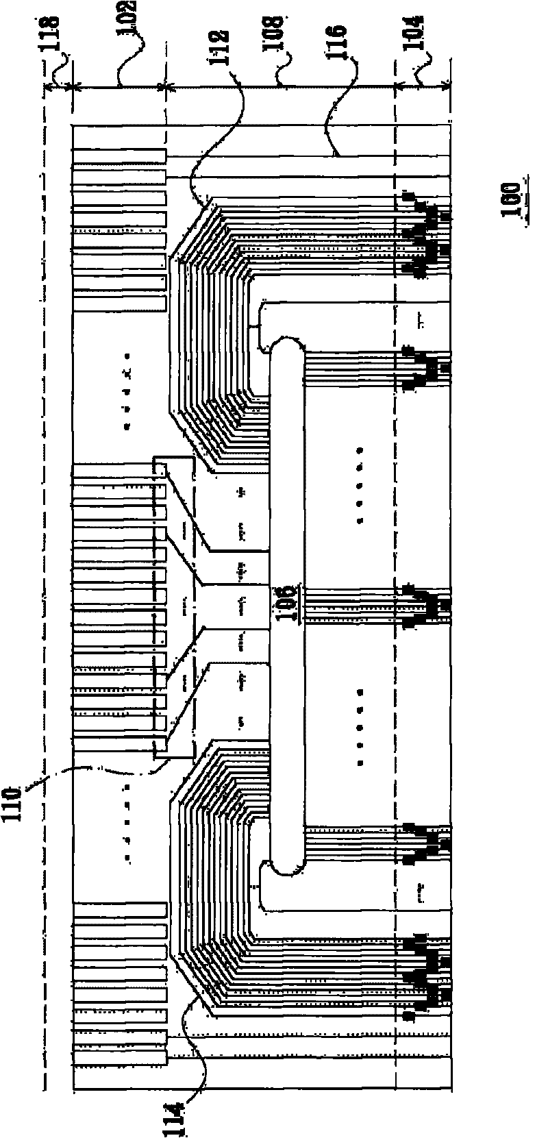
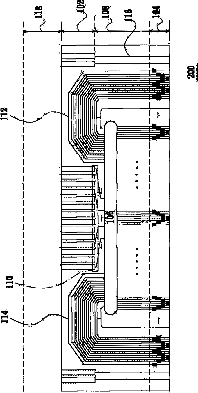
[0037] Please refer to figure 1 , Which shows a schematic diagram of a circuit board winding according to an embodiment of the present invention. The circuit board 100 is electrically coupled between two circuits, and includes a plurality of first pins 102, a plurality of second pins 104, a chip placement area 106 and a winding area 108. Among them, as those skilled in the art can easily know, the two circuits may be, for example, a printed circuit board of a display and a display area circuit, but they are not limited thereto.

[0038] In this embodiment, the first pin 102 is electrically coupled to one of the two circuits, and the first pin 102 may be, for example, a pad. The second pin 104 is electrically coupled to the other of the two circuits, and the second pin 104 can be, for example, a pin used to test whether the circuit board 100 can operate normally. Therefore, after the circuit board 100 is assembled, the second The pin 104 will be cut off.

[0039] The chip placeme...


PUM


Abstract

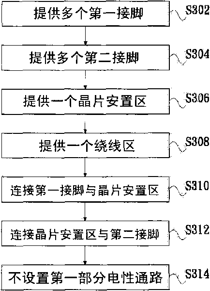
The invention relates to a layout method and a circuit board. The circuit board is electrically coupled between two circuits, and comprises a plurality of first pins, a plurality of second pins, a chip placement area and a winding area, wherein the first pins are electrically coupled to one of the two circuits; the second pins are electrically coupled to the other circuit; the chip placement area is used for holding circuit chips; and the winding area is used for arranging a plurality of electric accesses. Two ends of a first part of electric access in the electric accesses are respectively and electrically coupled to one of the plurality of first pins and the chip placement area; two ends of a second part of electric access in the electric accesses are respectively and electrically coupled to the chip placement area and one of the second pins; and any one of the first part of electric access is not arranged between the second part of electric access and at least one of the first pins.

Description

【Technical Field】 [0001] The present invention relates to a printed circuit board, and particularly relates to a layout method and a circuit board that can make full use of the space on the circuit board for winding. 【Background technique】 [0002] Please refer to Image 6 , Which shows a schematic diagram of the existing circuit board winding. In the prior art, the circuit board 600 is electrically coupled between the controller circuit and the display area circuit, and includes a first pin 602, a second pin 604, a chip placement area 606 and a winding area 608. [0003] The first pin 602 is electrically coupled to the controller circuit. The second pin 604 is electrically coupled to the display area circuit. The chip placement area 606 is used for placement of circuit chips. [0004] The winding area 608 includes a first portion of electrical vias 610, second portions of electrical vias 612 and 614, and a third portion of electrical vias 616. Among them, the first part of the el...

Claims


Application Information

Patent Timeline
IPC IPC(8): H05K1/02H05K1/11
Inventor 林勇旭许胜凯汪志松
Owner AU OPTRONICS CORP
Learn More