Method for puncturing iron core by motor wire-insertion preventing winding

A winding pair and iron core technology, which is used in the field of aviation motor embedding to prevent winding to iron core breakdown, can solve the problems of breakdown failure of winding withstand voltage test, easy damage of winding insulation, and breakdown of iron core insulation, etc. Processing quality and reliability, avoidance of insulation damage, the effect of large economic and social benefits

Inactive Publication Date: 2011-09-21
SHAANXI AVIATION ELECTRICAL
View PDF0 Cites 0 Cited by
  • Summary
  • Abstract
  • Description
  • Claims
  • Application Information

AI Technical Summary

Problems solved by technology

At present, the structure of the motor stator and rotor core with insulating end plates is that the stator and rotor core punching sheets are laminated into a stator or rotor core according to the requirements of the number of core laminations and the thickness of the stack, and then fastened. The insulating end plates are respectively glued to the two end faces of the stator or rotor iron core, and when inserting or winding the wires, the wrong piece in each inserting slot of the iron core is repaired and cleaned, and this traditional process is used for production and processing. The motor stator or rotor iron core has the most problems in the actual production of embedded wires. The insulation of the winding at the slot of the iron core is easy to damage, resulting in breakdown failure of the winding withstand voltage test, especially the small size of the winding end requires high withstand voltage value. After the embedded winding of the stator and rotor components of the aero-generator, the insulation breakdown of the winding to the core is more common

Method used


Image

  • Method for puncturing iron core by motor wire-insertion preventing winding
  • Method for puncturing iron core by motor wire-insertion preventing winding
  • Method for puncturing iron core by motor wire-insertion preventing winding

Examples


Embodiment Construction

[0024] Now in conjunction with embodiment, accompanying drawing, the present invention will be further described:

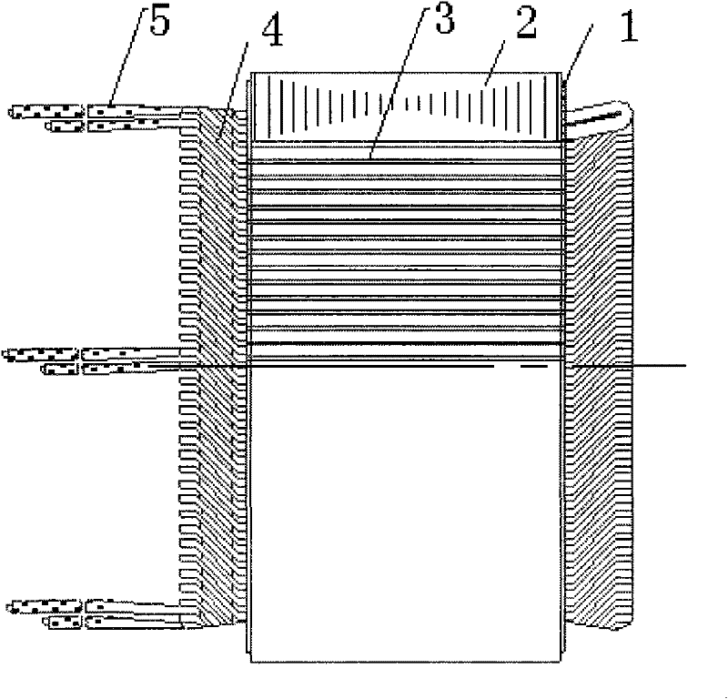
[0025] The embodiment is a DC starter generator. The compensation winding assembled by the stator adopts MYFB-0.13 double-strand wrapped flat copper wire with a specification of 1.25X5 to pass and wrap the embedded wire on the pole core.

[0026] 1. Stack the motor stator pole core punching sheets according to the number of stator pole core laminations and stack thickness requirements to form a stator pole core and fasten it with electron beam welding;

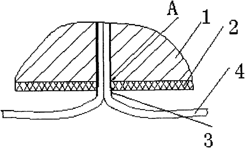
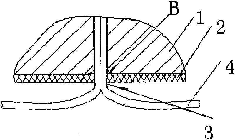
[0027] 2. File the rounded corners R0.8 around the slots at both ends of the stator magnetic pole core, and then glue the two insulating end plates with 204 glue to prevent the slots of the core during the wire embedding process. The sharp edge will damage the insulation of the groove and the outer insulation of the double-strand flat copper wire;

[0028] 3. During the wire embedding operation, leave a 1mm stra...


PUM


Abstract

The invention relates to a method for puncturing an iron core by a motor wire-insertion preventing winding, which is technically characterized in that: tips around the opening of wire-insertion grooves at two end faces of the iron core are firstly shaped into rounded corners R and an insulating end plate is then bonded when stators and rotors and magnetic pole iron core of the motor are manufactured; and the winding is led out of the opening of the end plate of the iron core with a particular linear section away from the end plate when the wire insertion for stator assembly and magnetic pole assembly is implemented so as to lower the possibility of causing the opening of the insulating end plate to deformation; the method according to the invention can effectively avoid the insulating damage of the winding after the wire insertion of the motor winding and guarantee the processing quality and the reliability of stator, rotor assemblies of the motor. Such technique is simple and economical in operation, easy for popularization and application, capable of bringing a great many economic and social benefits and suitable for the manufacturing of insertion winding assemblies, such as rotor assembly and stator assembly of the motor with the insulating end plate, etc.

Description

technical field [0001] The invention relates to a method for preventing the breakdown of a winding to an iron core by embedding wires of a motor, which belongs to the motor manufacturing technology and relates to a process for preventing the breakdown of a winding to an iron core by embedding wires of an aviation motor. Background technique [0002] The modern motor manufacturing industry has higher and higher requirements for the winding insulation performance of motor products, especially in the field of aviation motor manufacturing. The production of the stator and rotor assembly, the main core part of the motor, is to insert or wind the wires in the slots of the stator and rotor cores in accordance with the requirements of the motor design winding diagram. At present, the structure of the motor stator and rotor core with insulating end plates is that the stator and rotor core punching sheets are laminated into a stator or rotor core according to the requirements of the n...

Claims


Application Information

Patent Timeline
Patent Type & Authority Patents(China)
IPC IPC(8): H02K15/02H02K15/00
Inventor 张会强胡永嘉张丹
Owner SHAANXI AVIATION ELECTRICAL
Why Eureka
Try Eureka