Spring machine clamping system

A spring machine and adjustment system technology, applied in the field of parts, to achieve the effect of flexible feedback and flexible torque value

Inactive Publication Date: 2011-11-16
SHAOXING JIADU SPRING MACHINE
View PDF6 Cites 0 Cited by
  • Summary
  • Abstract
  • Description
  • Claims
  • Application Information

AI Technical Summary

Problems solved by technology

The existing problems are: firstly, it cannot provide flexible feedback information, and at the same time, it cannot be individually adjusted and controlled according to actual needs at any time. If the clamping force is set too small, the steel wire will slip and cannot move forward; if the clamping force is set too large, The precision of the spring manufacturing process is low and unstable, and the wear of the feeding groove wheel is large
[0004] Therefore, the most important thing is that it cannot meet the requirements of producing high-precision springs and needs to be improved.

Method used


Image

  • Spring machine clamping system
  • Spring machine clamping system
  • Spring machine clamping system

Examples


Embodiment Construction

[0024] The present invention will be further described below in conjunction with the accompanying drawings and embodiments.

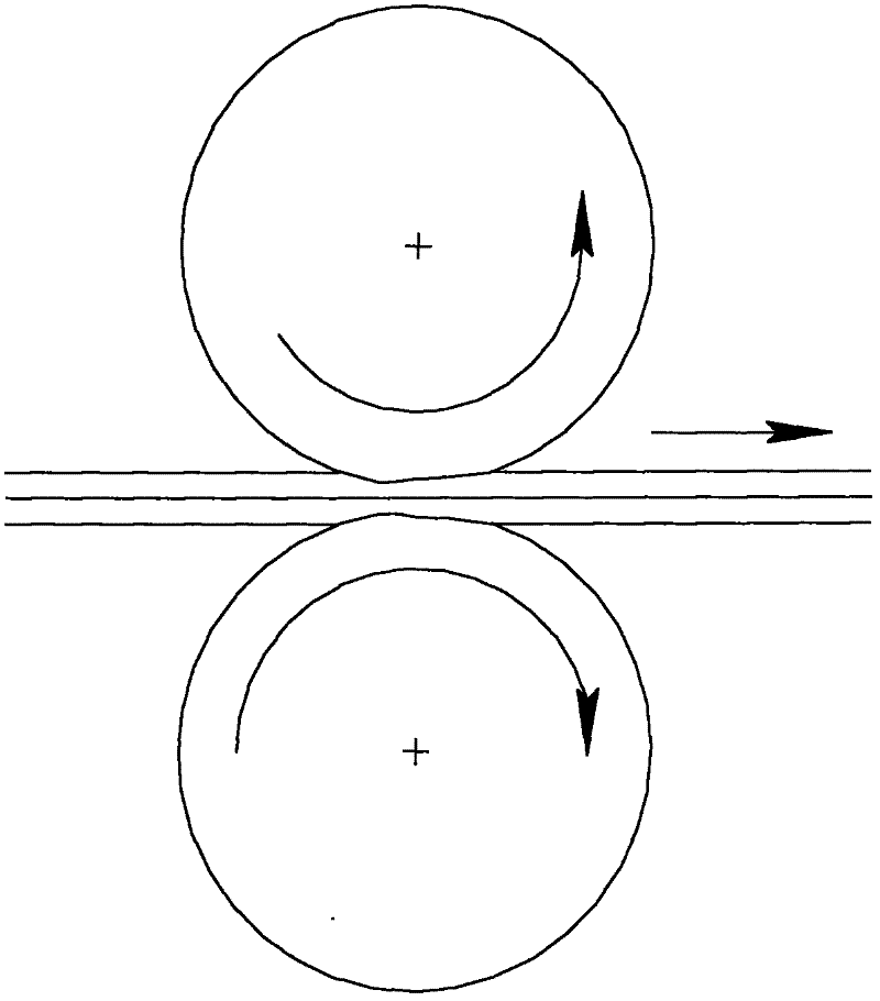
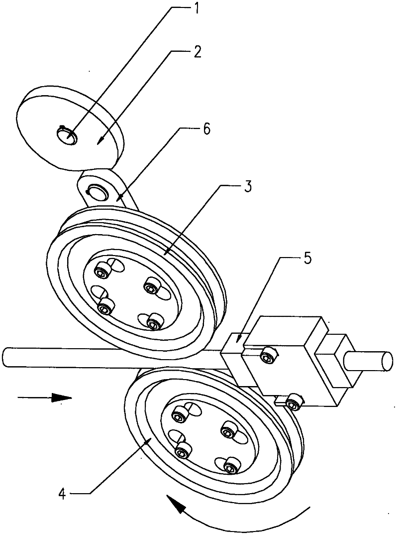
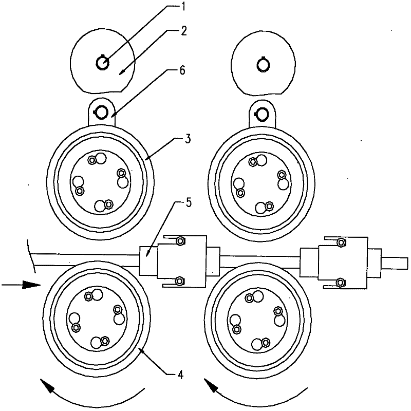
[0025] Such as Figure 1-Figure 3 Shown, a kind of preferred embodiment of the present invention comprises upper groove wheel 3 and lower groove wheel 4 that are arranged up and down, is used for the steel wire holding block 5 of clamping steel wire and is in close contact with cam device 2 all the time and with The sliding block 6 that upper groove wheel 3 rotating shafts are fixedly connected. It also includes a control adjustment system, including a deceleration device 8 arranged between the servo motor 1 and the cam device 2, and a feeding motor 7 connected with the grooved wheel. Wherein, each servo motor 1 and the cam device 2 are independently connected and set, so that the clamping force of each pair of upper and lower groove wheels on the steel wire can be automatically adjusted, and at the same time, individual upper and lower groove wheel gr...


PUM


Abstract

The present invention discloses a spring machine clamping system which comprises an upper groove wheel, a lower groove wheel, a steel wire grip block, a slide block and a control and adjustment system, wherein the upper groove wheel and the lower groove wheel are vertically arranged, the steel wire grip block is used for gripping steel wires, the slide block always close contacts a cam gear and is fixedly connected with a rotating shaft of the upper groove wheel, and the control and adjustment system comprises the cam gear , a feeding motor and a data wire, wherein the cam gear is fixedly installed on the rotating shaft and driven by a servomotor, the feeding motor and the groove wheels are in drive connection, the data wire is connected with an electronic control unit and used for transmitting data, wherein both the servomotor and the cam gear are in individual drive arrangement. The spring machine clamping system can be adjusted at any moment and individually controlled according to actual use requirements, and can flexibly feed back torque numerical values.

Description

technical field [0001] The invention relates to a component on a spring machine, in particular to a wire material feeding servo system of the spring machine. Background technique [0002] The wire feeding mechanism of the spring machine in the prior art generally adopts a hydraulic or pneumatic mechanism or tightens bolts to control the relative position of the feeding grooved wheels, and uniformly controls the clamping force of each group of feeding grooved wheels. The existing problems are as follows: firstly, it cannot provide flexible feedback information, and at the same time, it cannot perform individual adjustment and control at any time according to actual needs. If the clamping force is set too small, the steel wire will slip and cannot move forward; if the clamping force is set too large, Then the precision of the spring manufacturing process is low and unstable, and the feeding groove wheel wears a lot. [0003] Secondly, when the existing wire-feeding wheel cla...

Claims


Application Information

Patent Timeline
Patent Type & Authority Patents(China)
IPC IPC(8): B21F35/00B21F23/00
Inventor 俞家林
Owner SHAOXING JIADU SPRING MACHINE
Why Eureka
Try Eureka