Improved physical method for topographic correction of remote sensing images

A technique of terrain correction, physical method, applied in the field of remote sensing

Inactive Publication Date: 2010-06-02
CENT FOR EARTH OBSERVATION & DIGITAL EARTH CHINESE ACADEMY OF SCI
View PDF0 Cites 12 Cited by
  • Summary
  • Abstract
  • Description
  • Claims
  • Application Information

AI Technical Summary

Problems solved by technology

[0004] The purpose of the present invention is to provide an improved remote sensing image terra

Method used


Image

  • Improved physical method for topographic correction of remote sensing images
  • Improved physical method for topographic correction of remote sensing images
  • Improved physical method for topographic correction of remote sensing images

Examples


Embodiment Construction

[0014] 1. Calculation of direct solar radiation

[0015] The direct solar radiation received by a pixel on a slope surface can be converted from the direct radiation received by its corresponding horizontal pixel through cosine correction. The specific conversion formula is as follows:

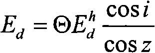
[0016] E d = Θ E d h cos i cos z (Formula 1)

[0017] In the formula: E d is the direct solar radiation received by the pixel on the slope, E d h is the direct solar radiation received by the pixel on the horizontal plane, obtained from the 6S model. i is the angle of incidence of the sun on the slope (the angle between the direct sunlight and the normal of the slope), and z is the zenith angle of the sun. Θ is the terrain shadow coefficient, if the slope is a shadow area (cosi<0), Θ is 0, otherwise it is 1; the...


PUM


Abstract

The invention relates to an improved physical method for topographic correction of remote sensing images, which considers the influence of the topography on incident irradiance and earth surface reflectivity received by the sloping surface, more accurately computes sky radiation received by the sloping surface pixel, and meanwhile considers the influence of atmosphere during the topographic correction. The method of the invention can obtain the better result of the topographic correction; and the method belongs to the physical method, has universality and can be applied to various optical remote sensing images.

Description

technical field [0001] The invention belongs to the technical field of remote sensing, and relates to the processing and application of remote sensing data. Background technique [0002] In rugged mountainous areas, the influence of terrain on the signals received by satellite sensors is manifested in two aspects: one is that the terrain affects the incident irradiance received by ground targets; the other is that the terrain changes the composition of the sun, the surface and satellite sensors The geometric structure of the ground target affects the reflectivity of the ground target in the direction of the satellite sensor. The corresponding terrain correction should also include two parts. Firstly, the total radiation received by the pixels on the horizontal plane is converted into the total radiation received by the pixels on the slope, which is called the incident irradiance correction (the total radiation received by the pixels on the slope includes Three parts: solar ...

Claims


Application Information

Patent Timeline
IPC IPC(8): G01S7/48
Inventor 张兆明何国金
Owner CENT FOR EARTH OBSERVATION & DIGITAL EARTH CHINESE ACADEMY OF SCI
Why Eureka
Try Eureka