Handle cover of a motor bicycle

A technology for motorized two-wheeled vehicles and handle covers, which is applied to bicycle racks, bicycle accessories, transportation and packaging, etc. It can solve the problems of complicated loading and unloading of the front half of the handle cover, and achieve the effect of improving appearance

Active Publication Date: 2010-06-09
HONDA MOTOR CO LTD
View PDF1 Cites 14 Cited by
  • Summary
  • Abstract
  • Description
  • Claims
  • Application Information

AI Technical Summary

Problems solved by technology

[0006] exist image 3 The headlight is installed in the opening (54) for the headlight of the front half of the handle cover (51) shown. Since the wire harness extends from the headlight, the installation and removal of the front half of the handle cover (51) becomes complicated.

Method used


Image

  • Handle cover of a motor bicycle
  • Handle cover of a motor bicycle
  • Handle cover of a motor bicycle

Examples


Embodiment 1

[0045] First, Embodiment 1 of the present invention will be described based on the drawings.

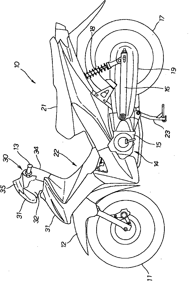
[0046] figure 1 It is a left side view of a motorcycle (motorcycle) of the present invention. A motorcycle 10 is a motorcycle having the following structure. A front wheel 11 is provided at the front of the vehicle, and a front wheel 11 is provided on the top of the front wheel 11. The fender 12 has a handle 13 for turning (steering) the front wheel 11 above the front fender 12, and an engine 14 is provided at the lower central part of the vehicle, and a swing arm (singa-arm) is arranged behind the engine 14. Mu) 16 has a freely rotatable rear wheel 17 at the rear of the swing arm 16, the swing arm 16 is biased downward by the rear buffer 18, and a drive chain chamber 19 is provided along the swing arm 16, and the rear wheel 17 has a seat 21 called a tandem seat, a vehicle has a body cover 22 , a body frame not shown has a center bracket 23 , and a handle 13 has a handle cover 30 ....

Embodiment 2

[0070] Next, Embodiment 2 of the present invention will be described based on the drawings.

[0071] Such as Figure 11 As shown, the front half body 32 of the handle cover is a resin molding with the following structure. It is T-shaped when viewed from the front of the vehicle, and has an engaging part 71 for screwing the front end of the upper handle cover in the center of the vehicle width direction. The central opening 72 of the engaging portion 71 has left and right sides (left in the figure means "right" in a V-shape) lamp openings 73L and 73R on the side surfaces of the central opening 72, and the openings for each lamp are provided. Above the openings 73L, 73R there are horizontally long maintenance openings 74L, 74R, on the right side of the right maintenance opening 74R there is an opening 75 for a storage tank, and between the left and right openings 73L, 73R for lamps. There are engaging portions 76 (such as two openings 73L across) for screwing position marker la...


PUM


Abstract

The invention provides a handle cover of a motor bicycle capable of easily maintaining and operating holding vessel in the handle cover. When only discharging the upper handle cover, a first opening portion (61) is exposed as the chart. The holding vessel is maintained by the first opening portion (61). It is not necessary to discharge the handle cover front part (32) from the handle cover back part (34). When the maintenance and the operation are end, the upper handle cover is covered. The first opening portion (61) and a joint surface (58) are covered by the upper handle cover to increase the beautification of the appearance.

Description

technical field [0001] The present invention relates to improvements in handle covers covering handles. Background technique [0002] It is known that in motorcycles (motorcycles), a handle for steering the front wheels is often provided with a storage tank for storing brake fluid. Moreover, the handle and the storage tank are covered with a handle cover mainly for the purpose of improving appearance (for example, refer to Patent Document 1.). [0003] As in Patent Document 1 Figure 4 As shown, a storage tank (44R) is installed on the handle (17) (symbols with parentheses indicate the symbols recorded in Patent Document 1. The same applies below), and the front half of the handle cover (51) and the rear half of the handle cover The handle cover formed by the body (52) surrounds the storage tank (44R) and the handle (17). The oil amount confirmation window (69) of the reservoir tank (44R) can be seen from the outside through the opening (59R). [0004] As a result of conf...

Claims


Application Information

Patent Timeline
Patent Type & Authority Applications(China)
IPC IPC(8): B62K19/48
Inventor 五十岚逸雄清治达也田中纯中野润一
Owner HONDA MOTOR CO LTD
Why Eureka
Try Eureka