Automatic drainage system for cable tunnel

A technology for cable tunnels and automatic drainage, applied in drainage, non-electric variable control, control/regulation systems, etc., can solve the problems of cable tunnels and tunnel facilities hazards, and achieve the effect of ensuring safety and realizing automatic control of drainage systems.

Inactive Publication Date: 2010-06-09
牡丹江电业局
View PDF0 Cites 18 Cited by
  • Summary
  • Abstract
  • Description
  • Claims
  • Application Information

AI Technical Summary

Problems solved by technology

If the water volume is large or the drainage is not timely, it...

Method used


Image

  • Automatic drainage system for cable tunnel
  • Automatic drainage system for cable tunnel
  • Automatic drainage system for cable tunnel

Examples


Embodiment Construction

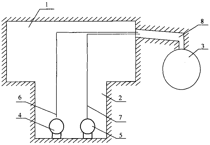
[0010] 1. dig a collecting well (2) at the lowest part of the cable tunnel (1), install two submersible pumps in the collecting well: submersible pump A (3), submersible pump B (4), connect the cable tunnel (1) and The main drainage pipe (3) is dug through, and the connecting pipe (8) is made with a cement pipe. Then connect the water outlet of the submersible pump to the main drainage pipe.

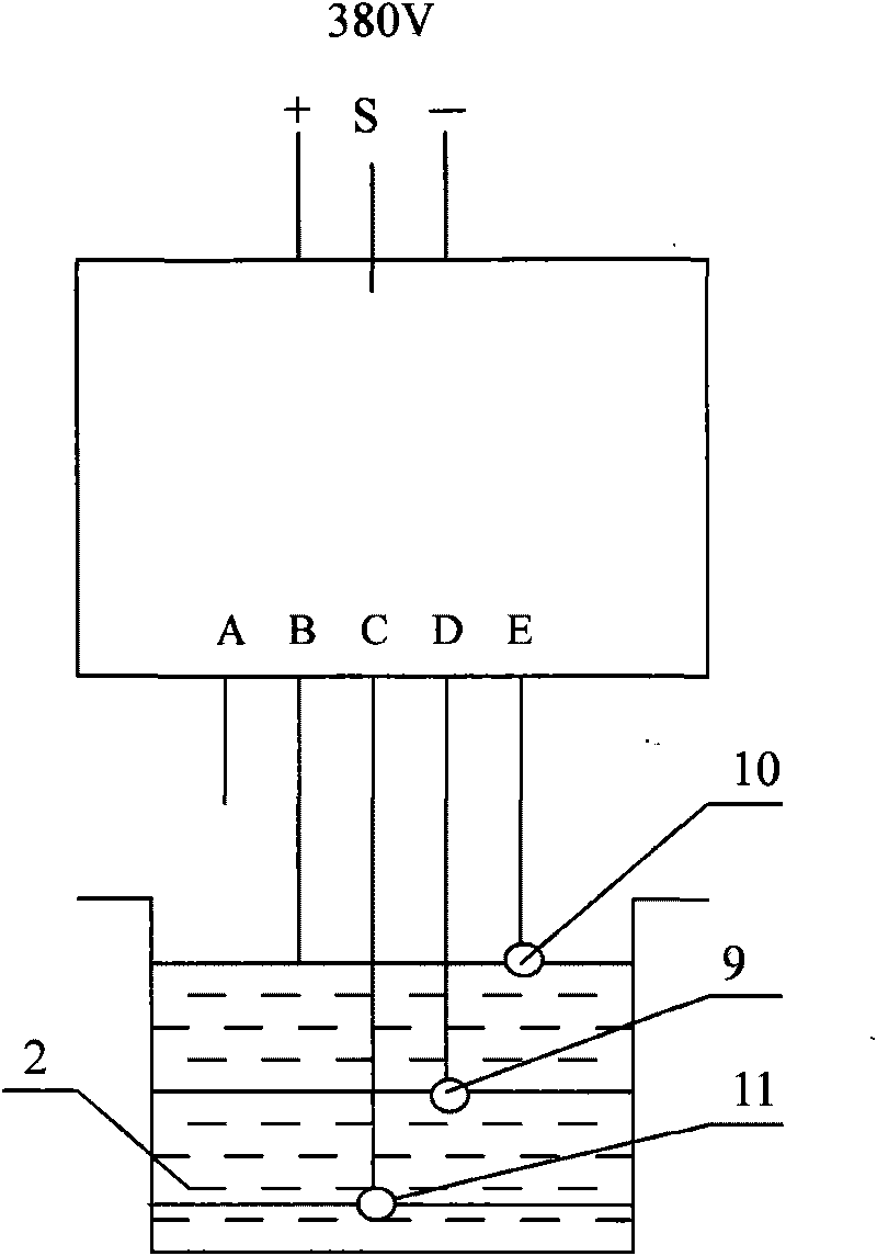
[0011] 2. E- is the high water level control point of the water collection well. When the water level rises to point E, the water contacts the high water level probe (9), and the water level controller automatically turns on the submersible pump B (7). D- is the low water level control point of the sump well, if the water level drops below the D point water level, the low water level probe (8) is out of contact with the water, and the water level controller automatically closes the submersible pump B (7). When the water level rose to point D, the low water level probe (8) was in contact...


PUM


Abstract

The invention relates to a automatic drainage system for a cable tunnel, which belongs to the field of drainage. The cable tunnel automatic drainage system comprises a cable tunnel (1), a water collecting well (2), a main drainage pipeline (3), a submersible pump A (4), a submersible pump B (5), a high water level probe (9), a low water level probe (10), a zero water level probe (11), and the like. In low water level, the submersible pump A (4) is started to drain water; and in high water level, the submersible pump B (5) is simultaneously started to drain water. The invention has the advantages of high automation degree, timely drainage and large drainage amount and forcefully ensures that the cable in a tunnel is safe.

Description

technical field [0001] The invention relates to the drainage field, in particular to an automatic drainage system for cable tunnels. Background technique [0002] At present, the known drainage of cable tunnels adopts artificial drainage. And artificial drainage cannot solve the needs of a large amount of stagnant water and rainy day drainage at all. If the water volume is large or the drainage is not timely, it will cause harm to the cable tunnel and the facilities in the tunnel. Contents of the invention [0003] In order to overcome the shortcomings of the existing drainage methods, the automatic drainage system of the present invention can effectively solve the problem, and can discharge a large amount of accumulated water and rainwater in time, effectively ensuring the safety of the tunnel and internal equipment. [0004] The technical solution adopted by the present invention to solve the technical problem is: dig a water collection well (2) at the lowest point of ...

Claims


Application Information

Patent Timeline
IPC IPC(8): E21F16/02G05D9/12
Inventor 佟英男孙国强杨艳秋
Owner 牡丹江电业局
Why Eureka
Try Eureka