Manufacturing mold of structural surface model in direct shear test

A structural surface and mold technology, applied in the engineering field, can solve problems such as poor fit between the upper and lower plates, high cost, and inability to make multiple scales, and achieve high-precision results

Inactive Publication Date: 2010-06-09
ZHEJIANG UNIVERSITY OF SCIENCE AND TECHNOLOGY
View PDF0 Cites 24 Cited by
  • Summary
  • Abstract
  • Description
  • Claims
  • Application Information

AI Technical Summary

Benefits of technology

This patented technology allows for creating accurate structures by accurately simulating different types of rocks under various conditions such as stress or strain levels without requiring expensive equipment like laboratory tests. It achieves this through making sure each part matches perfectly during manufacturing process.

Problems solved by technology

This technical problem addressed by this patented method relates to improving the accuracy of testing rocks' properties when they have undergone physical impacts or other external influences on their structure. Traditional methods involve directly measuring these forces without considering any differences among them due to imperfections in manufacture processes used for materials like concrete. However, there may also exist variations within certain types of material called lithium carbonate (LiC2), making accurate assessment challenging even more than just simply observing changes over time.

Method used


Image

  • Manufacturing mold of structural surface model in direct shear test
  • Manufacturing mold of structural surface model in direct shear test
  • Manufacturing mold of structural surface model in direct shear test

Examples


Embodiment Construction

[0020] The present invention will be further described below in conjunction with the accompanying drawings.

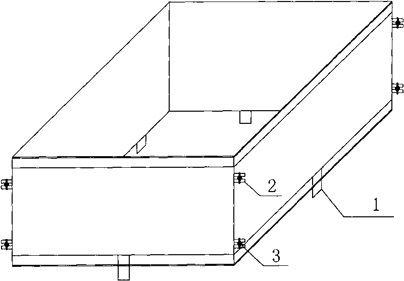
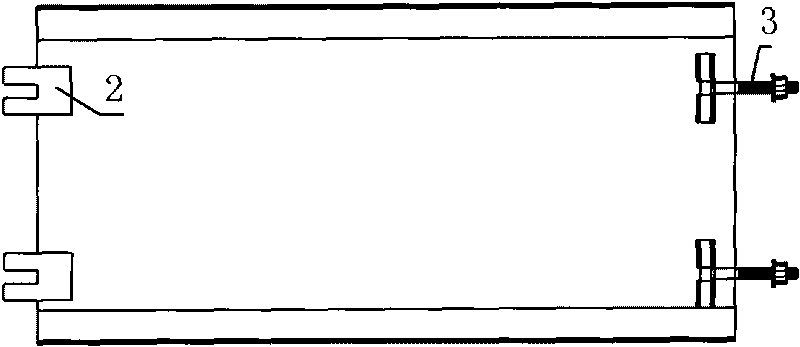
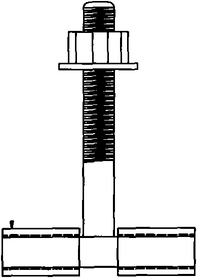
[0021] refer to figure 1 ~ Fig. 4, a kind of making mold of direct shear test structure surface model, comprises upper plate mold, lower plate mold and alignment pin, described upper plate mold is positioned on described lower plate mold, the side plate bottom surface of described upper plate mold There are positioning pins 1 for centering the upper plate mold and the lower plate mold. The upper plate mold includes an upper front side plate, an upper left side plate, an upper rear side plate and an upper right side plate. The upper plate mold forms The shape of the cavity matches the structural surface model of the upper plate to be made, the upper front side plate is fixedly connected with the upper left side plate and the upper right side plate, and the upper rear side plate is fixedly connected with the upper left side plate and upper right side plate The lower pla...


PUM


Abstract

The invention relates to a manufacturing mold of a structural surface model in a direct shear test, which comprises an upper disk mold, a lower disk mold and a positioning pin, wherein the upper disk mold is positioned on the lower disk mold; the positioning pin for centering the upper disk mold and the lower disk mold is arranged on the bottom surface of a side plate of the upper disk mold; the upper disk mold comprises an upper front side plate, an upper left side plate, an upper back side plate and an upper right side plate; the cavity shape formed by the upper disk mold is matched with the structural surface model of the upper disk to be manufactured; the upper front side plate is fixedly connected with the upper left side plate and the upper right side plate, and the upper back side plate is fixedly connected with the upper left side plate and the upper right side plate; the lower disk mold comprises a lower front side plate, a lower left side plate, a lower back side plate and a lower right side plate; the cavity shape formed by the lower disk mold is matched with the structural surface model of the lower disk to be manufactured; and the lower front side plate is fixedly connected with the lower left side plate and the lower right side plate, and the lower back side plate is fixedly connected with the lower left side plate and the lower right side plate. The manufacturing mold of the invention not only has the advantages of convenient operation, high speed and high accuracy but also can be used for manufacturing multi-scale structural surfaces of which the upper disks and the lower disks are completely matched.

Description


Claims


Application Information

Patent Timeline
Owner ZHEJIANG UNIVERSITY OF SCIENCE AND TECHNOLOGY
Why Eureka
Try Eureka