Receiving apparatus, moving angle estimation method, program and wireless communication system

A technology for receiving equipment and receiving signals, applied in radio wave measurement systems, direction finders using radio waves, radio wave director components and other directions, can solve the problems of increasing the size and cost of antenna equipment, and achieve the effect of reducing restrictions

Inactive Publication Date: 2010-06-09
SONY CORP
View PDF2 Cites 1 Cited by
  • Summary
  • Abstract
  • Description
  • Claims
  • Application Information

AI Technical Summary

Problems solved by technology

However, increasing the number of antennas results in an increase in device size and cost

Method used


Image

  • Receiving apparatus, moving angle estimation method, program and wireless communication system
  • Receiving apparatus, moving angle estimation method, program and wireless communication system
  • Receiving apparatus, moving angle estimation method, program and wireless communication system

Examples


no. 1 example

[0031] 1.1 Wireless communication system according to the first embodiment

[0032] 1.2 Configuration of the receiving device according to the first embodiment

[0033] 1.3 Operation of the receiving device according to the first embodiment

[0034] 2. The second embodiment

[0035] 3. Summary and Supplement

[0036]

[0037] [1.1 Wireless Communication System According to First Embodiment]

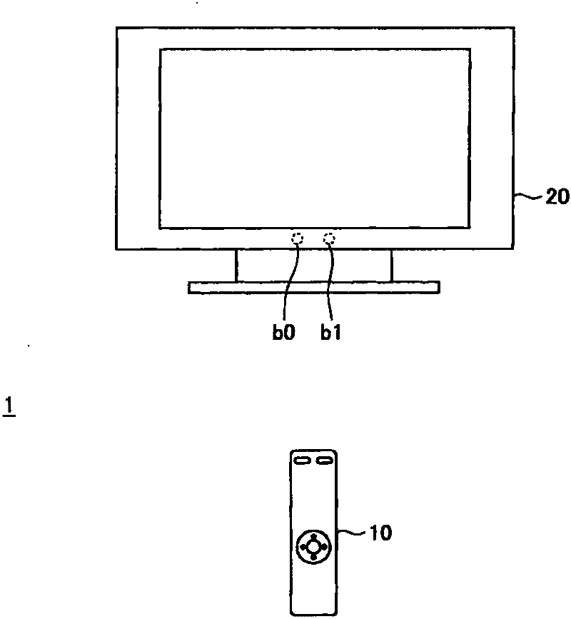
[0038] referenced below Figure 1 to Figure 4 The overall structure and gist of the wireless communication system 1 according to the first embodiment of the present invention are schematically described.

[0039] figure 1 is an explanatory diagram showing the overall configuration of the wireless communication system 1 according to the first embodiment of the present invention. refer to figure 1 , the wireless communication system 1 includes a transmitting device 10 and a receiving device 20 .

[0040] The transmitting device 10 wirelessly transmits packets in an intermittent ma...

no. 2 example

[0115] In the first embodiment as described above, two antennas b0 and b1 are mounted on the receiving device 20 . However, the number of antennas mounted on the receiving device 20 is not limited thereto. For example, the number of antennas may be three, as in the reception device 20' according to the second embodiment described hereinafter.

[0116] Figure 11 is an explanatory diagram showing an example of placement of antennas of the receiving device 20' according to the second embodiment of the present invention. refer to Figure 11 , on the receiving device 20' according to the second embodiment, the antenna b1 is placed at a distance dy from the antenna b0 in the Y direction, and the antenna b2 is placed at a distance dz from the antenna b0 in the Z direction. Figure 11 The spacing among the multiple antennas is schematically shown by way of illustration only, and the multiple antennas may actually be such as Figure 11 Shown are closer neighbors.

[0117] In this...


PUM


Abstract

A receiving apparatus is provided that includes a plurality of antennas, a phase difference calculation unit to calculate a phase difference of a received signal between the plurality of antennas, a difference calculation unit to calculate a difference between the phase difference of a previous received signal and the phase difference of a new received signal calculated by the phase difference calculation unit, and a moving angle estimation unit to estimate a moving angle of a transmitting apparatus from the difference in phase difference calculated by the difference calculation unit.

Description

technical field [0001] The present invention relates to a receiving device, a moving angle estimation method, a program and a wireless communication system. Background technique [0002] A receiving device including a plurality of antennas and estimating an arrival angle of a signal based on a phase difference of a carrier between the plurality of antennas has been proposed. Because if the interval between multiple antennas is equal to or longer than the half-wavelength of the carrier, the phase difference and angle of arrival of the carrier between multiple antennas are not one-to-one correspondence, so the interval between multiple antennas is usually designed to be equal to or shorter than that of the carrier. half wavelength. Therefore, for example, restrictions are imposed on the placement of antennas in a receiving device including three or more antennas. [0003] On the other hand, as the interval of the plurality of antennas becomes longer, the change in the phase ...

Claims


Application Information

Patent Timeline
Patent Type & Authority Applications(China)
IPC IPC(8): G01S3/12G01S3/48
CPCG01S3/48
Inventor 深田浩之
Owner SONY CORP
Why Eureka
Try Eureka