Connector

A technology of connectors and buckle parts, which is applied in the direction of connection, parts of connection devices, fixed/insulated contact members, etc., which can solve the problems of terminal holding force drop, damage, and falling out of the housing, etc.

Inactive Publication Date: 2010-06-09
BYD CO LTD
View PDF0 Cites 3 Cited by
  • Summary
  • Abstract
  • Description
  • Claims
  • Application Information

AI Technical Summary

Problems solved by technology

[0006] In actual use, there are certain problems in the above-mentioned holding method achieved by the interference between the barb and the plastic insulating shell. First, the structure interferes with and damages the upper wall 92 of the shell. In the process of repeatedly inserting and pulling out the FPC, it cannot To avoid continuous damage to the upper wall 92 of the housing, resulting in a decrea

Method used


Image

  • Connector
  • Connector
  • Connector

Examples


Embodiment 1

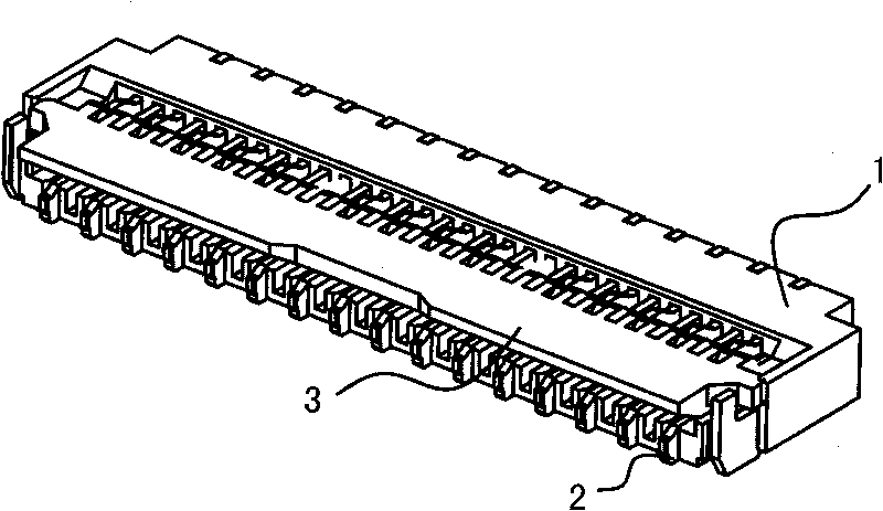
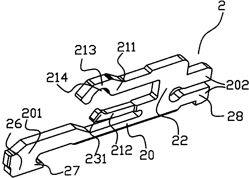
[0024] Such as Figures 2 to 4 As shown, the connector in the first embodiment of the present invention includes a housing 1 , terminals 2 held in the housing 1 , and a pressing member 3 . The housing 1 has an upper wall 10 and a lower wall 11, the front end 101 of the upper wall 10 and the front end 111 of the lower wall 11 constitute the front part 18 of the housing, the rear end 102 and the rear end 102 of the upper wall 11 The rear end portion 112 of the lower wall 11 constitutes the housing rear end portion 19 . The terminal has a fixing portion 20 substantially horizontally disposed along the lower wall 11 , and a clamping portion 21 disposed above the fixing portion, and the clamping portion 21 and the fixing portion 20 are connected by a connecting portion 22 .

[0025] In this embodiment, the clamping portion 21 includes a first elastic arm 211 and a second elastic arm 212 . The first elastic arm 211 extends substantially horizontally from the connecting portion 22 ...

Embodiment 2

[0033] Embodiment two of the present invention is as Figure 6 As shown, the first buckle part 40 is similar to the second buckle part 28 in the first embodiment, and the second buckle part 41 is similar to the hook-shaped first buckle part 27 in the first embodiment.

Embodiment 3

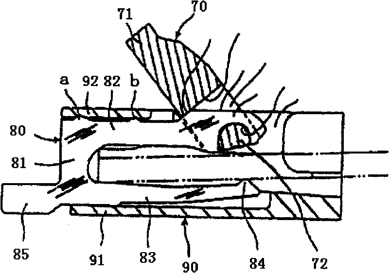
[0035] Embodiment three of the present invention is as Figure 7 As shown, the terminal shown is a seesaw-shaped terminal, the clamping portion is disposed at one end, the pressing member is disposed at the other end, and the fixing portion 64 is substantially horizontally disposed on the lower wall 52 . The pressing member includes a pulling part 71 and a cam 72 arranged at one end of the pulling part, and the cam has a longer axis and a shorter axis. The terminal has a first elastic arm 61 and a second elastic arm 62 connected to each other, one end of the first elastic arm 61 and the fixing portion 64 forms a clamping portion, and the cam 72 of the pressing member is held by the second The elastic arm 62 and the other end of the fixed part are limited. The first elastic arm 61 is connected to the second elastic arm 62 and connected to the fixed part 64 through the connecting arm 63. The first buckle part 65 of part 521 has the second buckle part 66 that is fastened to the ...


PUM


Abstract

The embodiment of the invention provides a connector which comprises a shell, a plurality of terminals and a pressing element, wherein the shell comprises an upper wall and a lower wall; the terminals are fixed in the shell, and the terminals are provided with a fixed part, a clamping part and a connecting part, wherein the fixed part is almost horizontally arranged along the lower wall, the clamping part is arranged above the fixed part and the connecting part is used for connecting the clamping part and the fixed part; and the position of the pressing element enables the pressing element to apply and release pressure to the clamping part, thereby forming an opening position for inserting an FPC (Flexible Printed Circuit) and a closing position for fixing the FPC. In the embodiment of the invention, the terminals are clamped and fixed in the insulating shell through arranging and respectively clamping a first buckling part and a second buckling part at the front part and the rear part of the shell, thereby better realizing the fixing of the terminals in the insulating shell, so that the upper wall and the lower wall can be manufactured to be thinner.

Description

technical field [0001] The utility invention relates to a connector, in particular to a connector used for electrical connection with FPC (Flexible Printed Circuit, flexible printed circuit). Background technique [0002] The structure of a typical FPC connector includes: several contact terminals with a clamping portion and an insulating housing for accommodating the terminals; a pressing member, usually with a cam, provided with an open and a closed position, when the pressing member is in the closed position When it is in the open position, the clamping part is loose and the FPC is easily pulled out of the connector. [0003] At present, the improvement of the FPC connector basically revolves around how to enhance the stability of the electrical connection, how to strengthen the holding strength of the terminal in the insulating housing, and how to reduce the thickness of the connector. [0004] Such as figure 1 A kind of existing FPC connector shown, comprises the insu...

Claims


Application Information

Patent Timeline
IPC IPC(8): H01R12/24H01R12/38H01R13/42H01R13/629
Inventor 周建刚
Owner BYD CO LTD
Why Eureka
Try Eureka