Equipment installation structure

A technology for equipment installation and construction, applied to substations/switchgear boards/panels/desks, etc., can solve the problem of time-consuming installation and operation of circuit breakers

Inactive Publication Date: 2010-06-09
KAWAMURA ELECTRIC INC
View PDF2 Cites 0 Cited by
  • Summary
  • Abstract
  • Description
  • Claims
  • Application Information

AI Technical Summary

Problems solved by technology

[0008] However, according to the conventional mounting structure, since the mounting table 52 is mounted using the screws 54, there is a problem that it takes time to mount the circuit breaker.

Method used


Image

  • Equipment installation structure
  • Equipment installation structure
  • Equipment installation structure

Examples


Embodiment

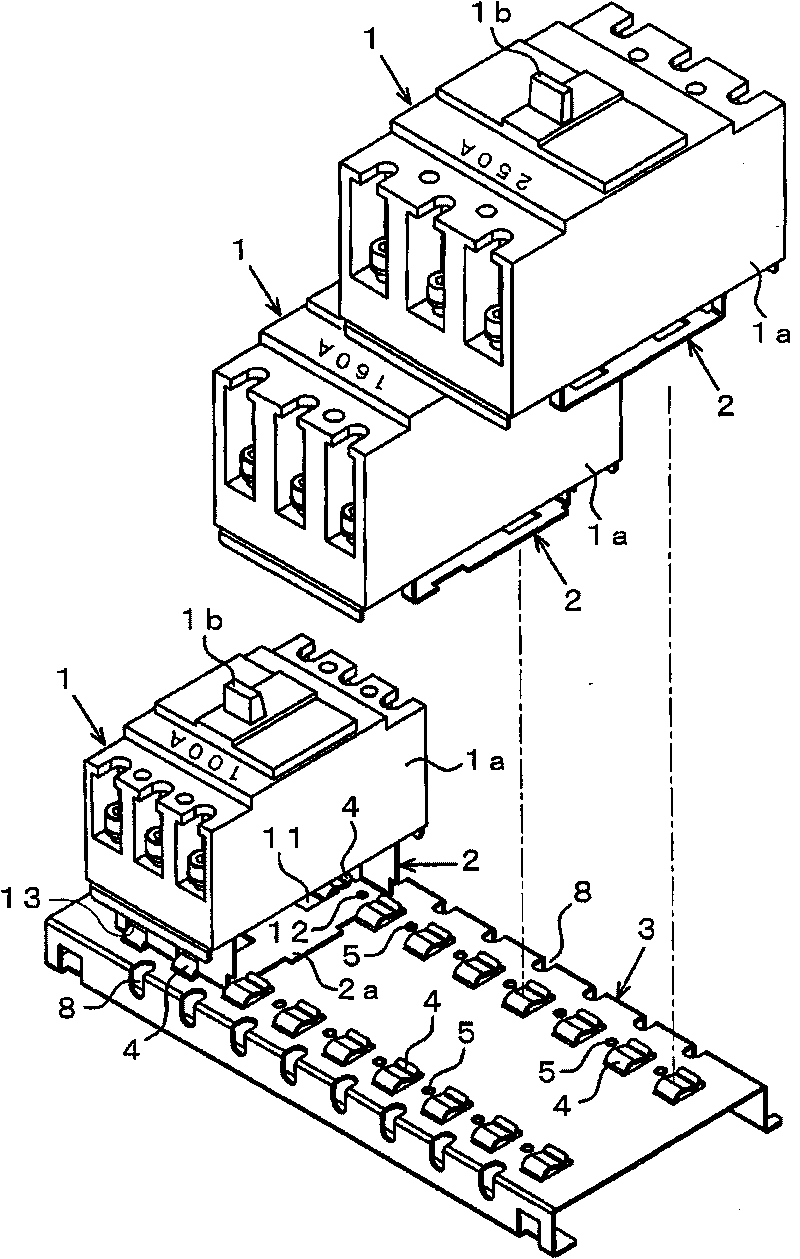
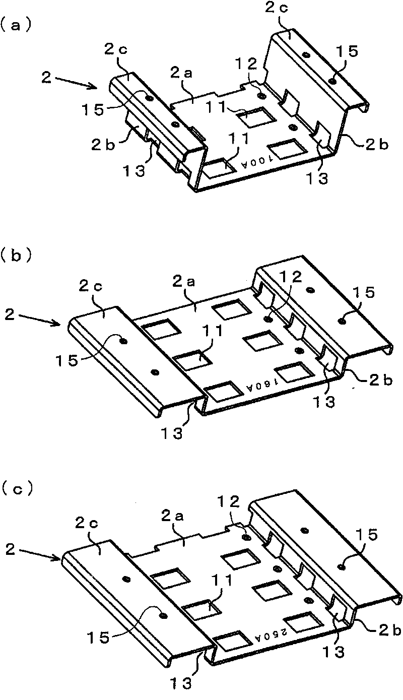
[0037] Such as figure 1 As shown, in the circuit breaker installation structure of this embodiment, three circuit breakers 1 are installed on a common bottom plate 3 via respective installation platforms 2 . Each circuit breaker 1 has a frame 1a having external dimensions corresponding to the load capacity (100A, 160A, 250A), and a handle 1b is provided on the upper surface of the frame 1a. Each mounting table 2 is formed with substantially the same planar area as the bottom area of ​​the frame 1a, and the bottom plate 3 is formed in a size capable of mounting three mounting tables 2 thereon.

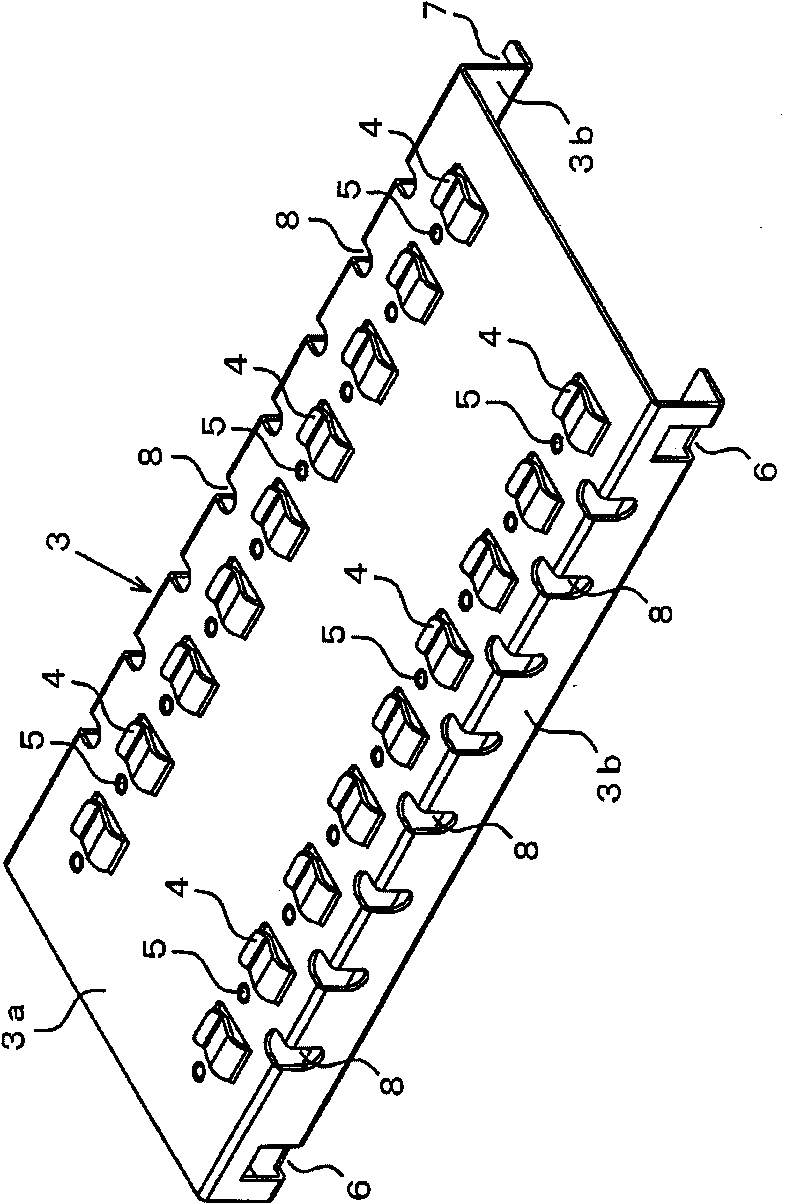
[0038] Such as figure 2 As shown, the bottom plate 3 is formed by bending a metal plate, and is provided with a flat surface portion 3a on which the mounting base 2 is placed and a pair of leg portions 3b mounted on a switchboard (not shown). On the planar portion 3a, a plurality of clamping pieces 4 and the same number of stoppers 5 are formed in two rows at equal intervals along t...


PUM


Abstract

The invention provides an equipment installation structure which mounts a plurality of equipment with different overall sizes on the same base plate by respective installation platforms, wherein the installation platforms with different sizes according to the equipment are simply and reliably installed on the base plate without screws. A plurality of clamping sheets (4) and stopping elements (5) are formed on the base plate (3); and the installation platform (2) is provided with bottom holes (11) and transverse hole (13) for the clamping sheets (4) to insert in and clamping and fixing parts (12) clamped and fixed on the stopping elements (5). The installation platform (2) slides on the base plate (3), the clamping sheets (4) generate elastic deformation by the bottom wall (2a) of the installation platform (2) to position the clamping and fixing part (12) on the stopping elements (5), and the bottom wall (2a) is clamped on the base plate (3) by the elastic restoring force of the clamping sheets (4).

Description

technical field [0001] The present invention relates to a structure in which a plurality of devices such as circuit breakers and switches are mounted on a common base plate. Background technique [0002] A switchboard for indoor wiring is provided with a plurality of circuit breakers with different load capacities according to user needs. A circuit breaker usually has a frame or a case with different dimensions depending on the load capacity. Conventionally, there is known a circuit breaker mounting structure in which a plurality of circuit breakers having different external dimensions are mounted on respective mounting stands, the mounting stands are mounted on a common base plate for each circuit breaker, and the base plate is installed inside the switchboard. [0003] For example, in the case of installing three circuit breakers with different load capacities, such as Figure 11 As shown, three mounts 52 are mounted on a common base plate 53 with screws 54 . Each mounti...

Claims


Application Information

Patent Timeline
Patent Type & Authority Applications(China)
IPC IPC(8): H02B1/04
Inventor 李杰华王顺民裘许敏赵霞
Owner KAWAMURA ELECTRIC INC
Why Eureka
Try Eureka