Conveyer

A technology for conveying devices and conveying parts, which is applied in the direction of conveyors, conveyor objects, transportation and packaging, etc., and can solve problems such as defects and container cover damage

Active Publication Date: 2010-06-16
KRONES AG
View PDF4 Cites 14 Cited by
  • Summary
  • Abstract
  • Description
  • Claims
  • Application Information

AI Technical Summary

Problems solved by technology

This often leads to failures due to crushing or interference of the container closures, which can lead to destruction and / or defects of the corresponding container closures during the further processing of the container closures
These drawbacks are due to the use of inelastic mechanical entrainment elements, large speed differences between the conveying element and the feed track, the opposite velocity vectors of the conveying element and the container caps during transfer, and when introducing the container caps into the A strong direction reversal that occurs at moments in the trough

Method used


Image

  • Conveyer
  • Conveyer
  • Conveyer

Examples


Embodiment Construction

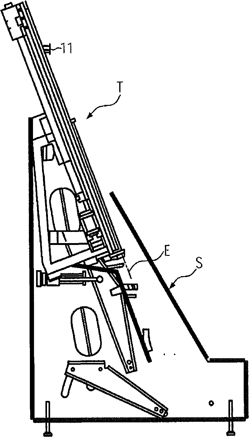
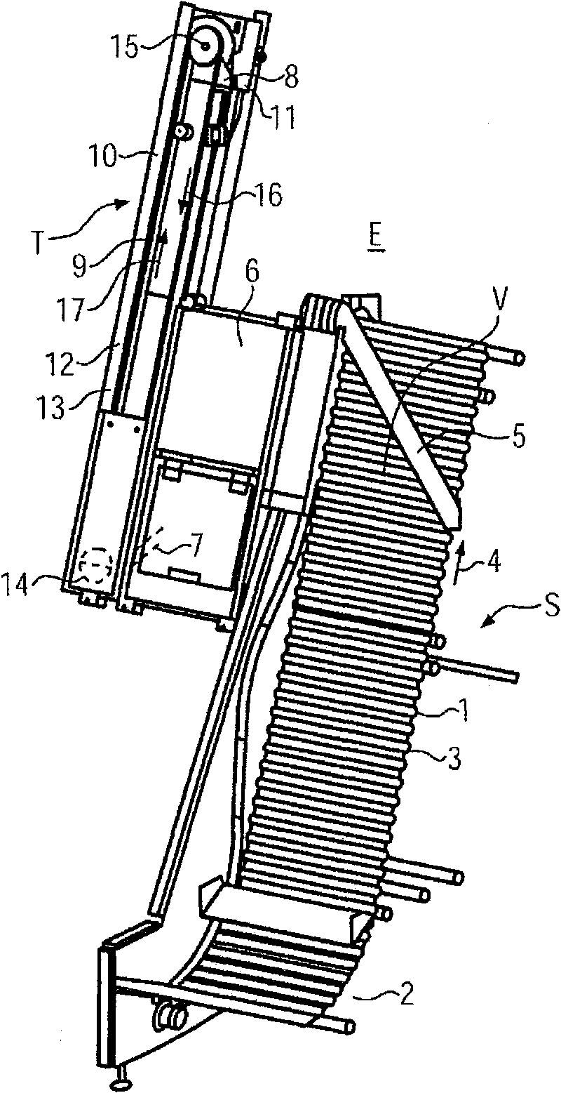
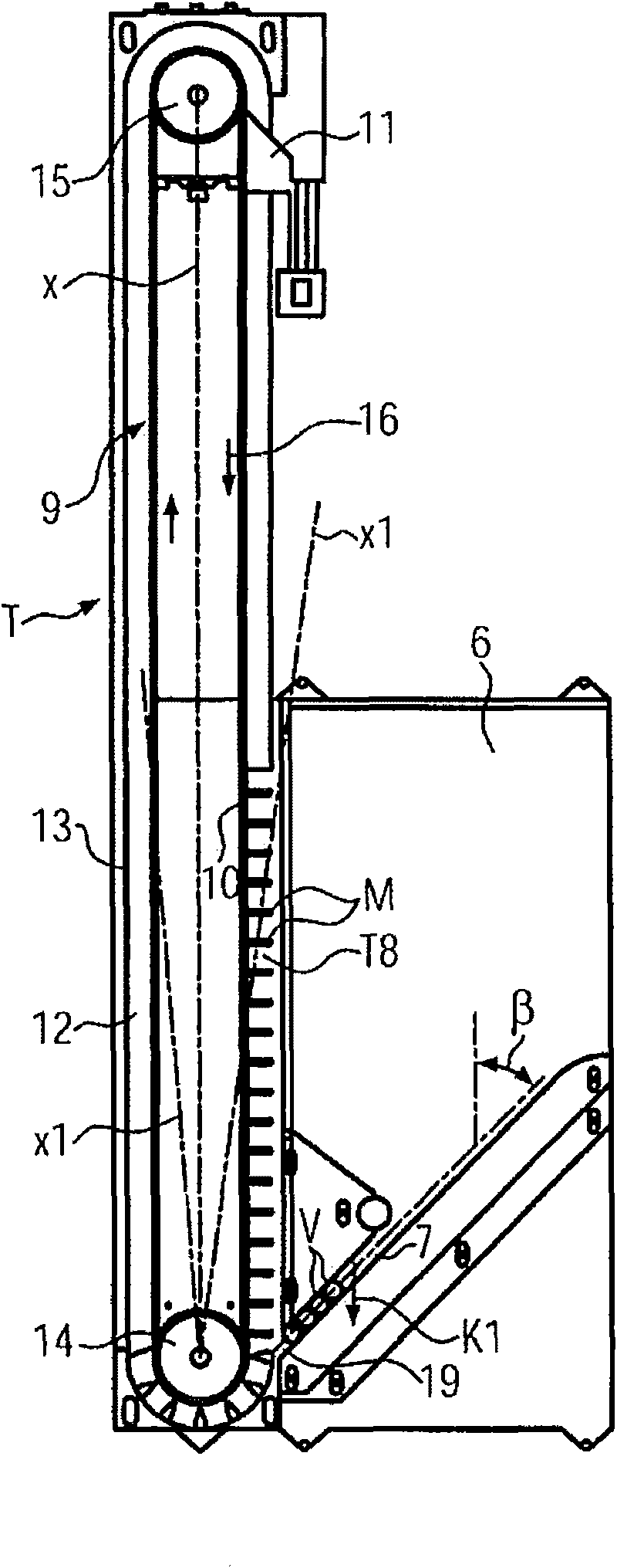
[0033] In container handling machines used in the beverage filling industry or in container closure systems, it is often necessary to sort container closures in piece goods and supplied in any orientation into a single orientation and to sort the sorted containers in the processing sequence of the corresponding machine The cover is conveyed upwards to the designated high position. In this regard, it is known to use the figure 1 and figure 2 The sorting unit S and the conveying device T are shown, wherein the sorting unit S and the conveying device T cooperate with each other functionally.

[0034] The sorting unit S comprises, for example, a webbing 1 with strip-like entrainment members 3 extending transversely, and enables the removal of container closures V initially provided in random orientations from the reservoir 2 below. Due to the rising movement of the webbing 1 of increasing steepness, each container lid V will be correctly oriented under the action of gravity with ...


PUM


Abstract

The present invention provides a conveyer (T) used for a container cover (V), which comprises an ascending circulating conveyor (9) that is provided in an ascending plane (E) and is provided with clip band components (M) on the conveying component (10). The conveying component (10) operates on an upper deflecting device and a lower deflecting device (14, 15). Each clip band component (M) projects from the external surface of the conveying component (10) basically with a right angle and limits an opening groove (18) used for the container cover (V). The conveyer (T) furthermore comprises at least one feeding rail (7). The feeding rail (7) is provided adjacently with the lower deflecting device (14) and conveys each container cover to the groove (18) with a downward component motion (K1). Furthermore the conveyer (T) comprises at least one unloading area (11) above the feeding rail. The conveyor is designed so that each clip band component (M) can move and / or deform from a position which is at least approximately perpendicular with the external surface of the conveying component (10) along a conveying direction (16) and / or a direction inverse to the conveying direction (16) at least through an elastic resetting mode.

Description

technical field [0001] The invention relates to a conveying device of the type stated in the preamble of claim 1 . Background technique [0002] In a container cap conveying device known from EP-A-1072513, the ascending circular conveyor is a chain conveyor, and an L-shaped non-elastic entraining element (entraining element) is connected on its conveying part, each of which entrains The shorter L-shaped legs of the components are connected such that the longer L-shaped legs protrude approximately perpendicularly from the outer side of the conveying component. The feed track feeds the container caps into the slot where the container caps are placed horizontally on said feed rail with their bottoms or openings facing down, so that each container cap is such that the container cap The bottom or opening portion rests directly on the longer L-shaped leg of the entrainment member in such a manner that it rests directly on the longer L-shaped leg of the entrainment member. The co...

Claims


Application Information

Patent Timeline
Patent Type & Authority Applications(China)
IPC IPC(8): B65G17/12B65G17/32B65G17/34B65G17/42B65G15/30B65G47/14B65G47/34
CPCB65G47/57B65G47/1471
Inventor 克劳斯·布赫浩斯蒂诺·西克特
Owner KRONES AG
Why Eureka
Try Eureka