Coupling apparatus between drive shaft and driven shaft

A driven shaft and driving shaft technology, applied in the field of couplings, can solve problems such as cost increase, difficulty, and work difficulty

Inactive Publication Date: 2010-06-16
KIA MOTORS CORP +1
View PDF8 Cites 4 Cited by
  • Summary
  • Abstract
  • Description
  • Claims
  • Application Information

AI Technical Summary

Problems solved by technology

[0007] The first is designed and manufactured so that the driving shaft and the driven shaft are arranged coaxially; however, it is difficult to arrange them substantially coaxially, and as the accuracy of the coaxiality increases, the work becomes very difficult and the cost increases rapidly

Method used


Image

  • Coupling apparatus between drive shaft and driven shaft
  • Coupling apparatus between drive shaft and driven shaft
  • Coupling apparatus between drive shaft and driven shaft

Examples


Embodiment Construction

[0029] Reference will now be made in detail to various embodiments of the invention, examples of which are illustrated in the accompanying drawings and described below. While the invention will be described in conjunction with exemplary embodiments, it will be understood that present description is not intended to limit the invention to those exemplary embodiments. On the contrary, the invention is intended to cover not only the exemplary embodiments, but also various alternatives, modifications, equivalents and other embodiments, which may be included within the spirit and scope of the invention as defined by the appended claims .

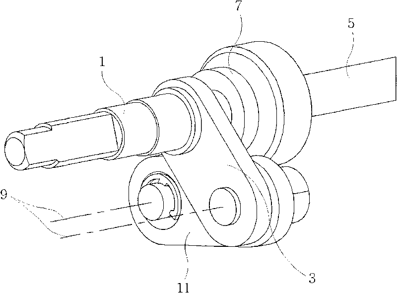
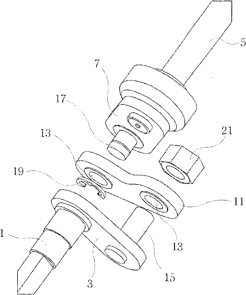
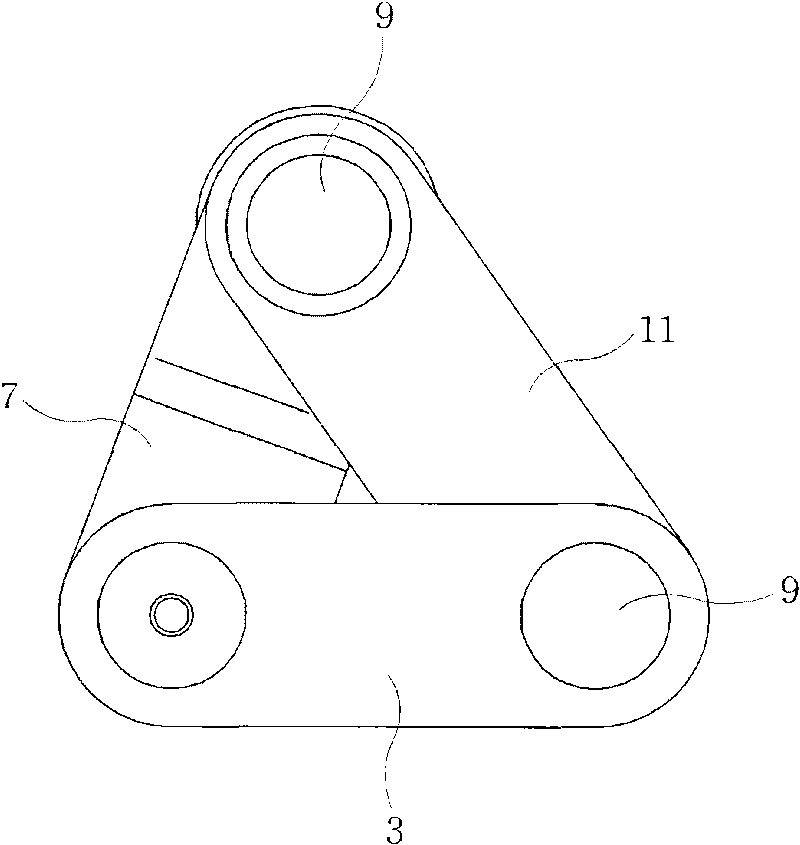
[0030] refer to Figure 1 to Figure 5 , according to an exemplary embodiment of the present invention, the coupling for the driving shaft and the driven shaft includes: the driving rod 3, which extends along the radial direction of the driving shaft 1, while being restricted to rotate relative to the driving shaft 1; The rod 7 extends along the ...


PUM


Abstract

A coupling for a driving shaft and a driven shaft may include a driving lever that extends in a radial direction from the driving shaft and being limited in rotation with respect to the driving shaft, a driven lever that extends in a radial direction from the driven shaft and being limited in rotation with respect to the driven shaft, and a connecting member that has two different rotational shafts spaced with a predetermined distance and pivotally coupled to one end portion of the driving lever and one end portion of the driven shaft respectively.

Description

[0001] Cross References to Related Applications [0002] This application claims priority from Korean Application Serial No. 10-2008-0113846 filed on November 17, 2008, the entire contents of which are hereby incorporated by reference for all purposes. technical field [0003] The present invention relates to a coupling for a driving shaft and a driven shaft, and more particularly, to a coupling that enables smooth and stable transmission of power even if the driving shaft and the driven shaft are eccentric. Background technique [0004] An active device, such as a motor, that transmits a rotational force to a shaft is required to drive a valve that opens / closes a flow passage through rotation of the shaft. [0005] Therefore, a coupling that transmits a rotational force generated from a rotational shaft of the motor (driving shaft) to a shaft of the valve (driven shaft) is required between the motor and the valve, wherein the motor is the driving device and the valve is the...

Claims


Application Information

Patent Timeline
Patent Type & Authority Applications(China)
IPC IPC(8): F16D1/02
CPCF16H21/12F16D3/04F16D1/02F16D1/00
Inventor 郑灿石
Owner KIA MOTORS CORP
Why Eureka
Try Eureka