Shaft sleeve oil groove machining lathe

A technology for processing machine tools and processing mechanisms, which is applied in the direction of metal processing machinery parts, metal processing equipment, manufacturing tools, etc., and can solve the problems of difficult tool stroke control, increased costs, and high requirements for workers' manipulation skills.

Inactive Publication Date: 2019-02-15
泉州市金典机械发展有限公司
View PDF11 Cites 2 Cited by
  • Summary
  • Abstract
  • Description
  • Claims
  • Application Information

AI Technical Summary

Problems solved by technology

Although this device is simple, it has the following disadvantages: 1. It is difficult to control the stroke of the tool, and it is difficult to ensure the depth and width of the oil groove during processing. Workers have high requirements for manipulating skills; 3. Long processing time and low production efficiency make it difficult to meet high-efficiency and large-volume production requirements

Method used


Image

  • Shaft sleeve oil groove machining lathe
  • Shaft sleeve oil groove machining lathe
  • Shaft sleeve oil groove machining lathe

Examples


Embodiment Construction

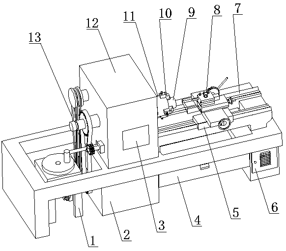
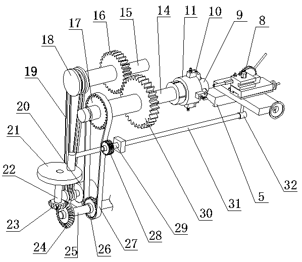
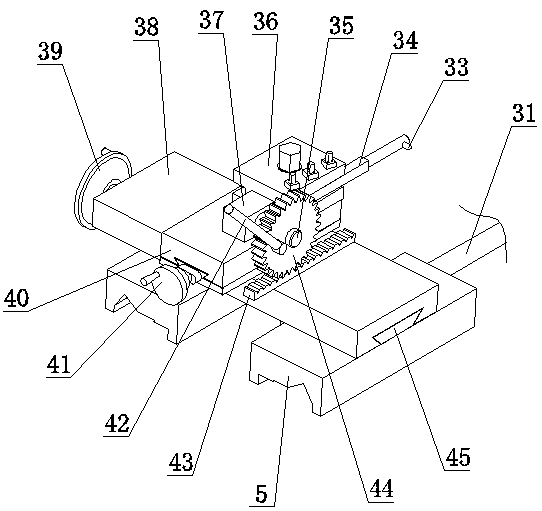
[0020] refer to Figure 1 to Figure 4 A shaft sleeve oil groove processing machine tool of the present invention will be further described.

[0021] A shaft sleeve oil groove processing machine tool, comprising a frame 2, a headstock 12, a guide rail 7, a transmission mechanism 13, and an oil groove processing mechanism 8, the headstock 12 is located above the frame 2, and an operation panel 3 is arranged on the front thereof, Described guide rail 7 is arranged on the right side of main shaft box 12, and its below is provided with waste box 4, and the right end of described frame 2 is provided with storage box 6, and described transmission mechanism 13 comprises motor 20, driven shaft one 15 , main shaft 14, driving shaft 25, driven shaft two 22, swing bar 31, the left end of described motor 20, driven shaft one 15 is all provided with pulley 18, and the outside of described pulley 18 is provided with belt 19, and described from Drive gear one 16 is provided in the middle of ...


PUM


Abstract

The invention discloses a shaft sleeve oil groove machining lathe. The shaft sleeve oil groove machining lathe comprises a rack, a main shaft box, a guide rail, a transmission mechanism and an oil groove machining mechanism. The shaft sleeve oil groove machining lathe is characterized in that the main shaft box is located below the rack, and the front face of the main shaft box is provided with anoperation panel; the guide rail is arranged at the right side of the main shaft box, and a waste material box is arranged below the guide rail; a storage box is arranged at the right end of the rack;the transmission mechanism comprises a motor, a first driven shaft, a main shaft, a driving shaft, a second driven shaft and a swing rod; the left end of the motor and the left end of the first driven shaft are each provided with a belt wheel; a belt is arranged at the outer sides of the belt wheels; a first driving gear is arranged in the middle of the first driven shaft; a first driven gear isarranged in the middle of the main shaft; a chuck is arranged at the right end of the first driven gear; and a second driving gear is arranged at the left end of the main shaft. By means of the shaftsleeve oil groove machining lathe, machining quality and efficiency of a shaft sleeve oil groove can be guaranteed; the labor intensity of workers is lowered; and the shaft sleeve oil groove machininglathe is reasonable in structural design and easy and convenient to operate.

Description

technical field [0001] The invention discloses a shaft sleeve oil groove processing machine tool, which belongs to the technical field of oil groove processing equipment. Background technique [0002] In the moving parts, the wear of the parts is caused by long-term friction. When the shaft and the hole are worn to a certain extent, the parts must be replaced. Therefore, it is necessary to choose a shaft sleeve with lower hardness and better wear resistance, which can reduce shaft and hole wear. For the wear of the seat, in order to better match the movement of the sleeve and the shaft, it is necessary to open an oil groove on the inner surface of the sleeve to achieve the purpose of lubricating and storing lubricating oil, so as to prevent the shaft from being aggravated or even damaged due to lack of oil. The conventional processing device of the oil groove is formed by turning the inner surface of the workpiece with the screw rod to drive the forming tool. Although this ...

Claims


Application Information

Patent Timeline
IPC IPC(8): B23B5/00B23Q5/10B23Q5/12B23Q5/38
CPCB23B5/00B23Q5/10B23Q5/12B23Q5/385
Inventor 陈超
Owner 泉州市金典机械发展有限公司
Why Eureka
Try Eureka