Cast-in channel

A technology of anchor rail and rail body, which is applied in the direction of construction and building construction, to achieve the effect of low manufacturing and simple cost

Inactive Publication Date: 2010-06-23
HILTI AG
View PDF5 Cites 7 Cited by
  • Summary
  • Abstract
  • Description
  • Claims
  • Application Information

AI Technical Summary

Problems solved by technology

[0005] A disadvantage of this known solution is that the individual anchor elements have to be inserted through the mounting opening and screwed in along the full length of the anchor bolt

Method used


Image

  • Cast-in channel
  • Cast-in channel
  • Cast-in channel

Examples


Embodiment Construction

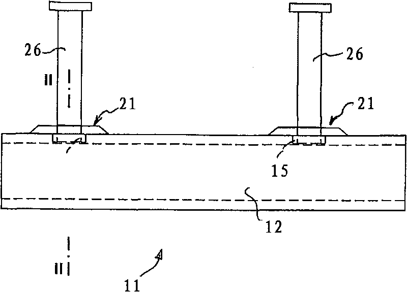
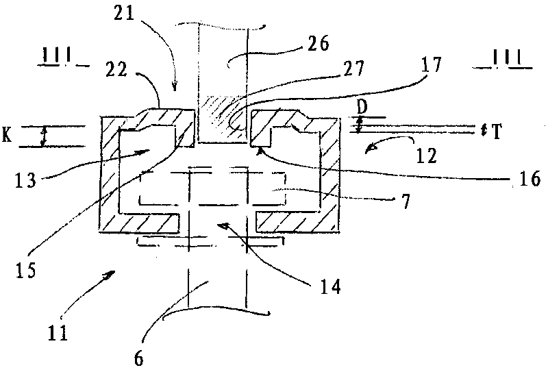
[0023] Figures 1 to 3 The anchor rail 11 shown in has a rail body 12 and a plurality of anchor elements 26 fastened thereon. The rail body 12 forms a receiving space 13 for receiving the tie element 7 for fastening the fastening element 6 on the anchor rail 11, wherein the receiving space 13 is accessible from the outside through a mounting opening 14 extending in the longitudinal direction of the rail body 12 .

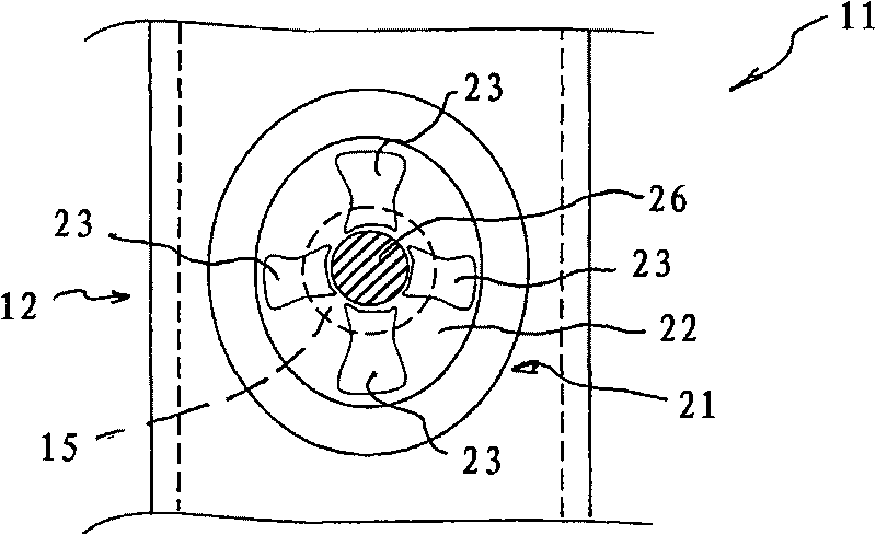
[0024] Two outwardly directed recesses 21 are provided on the rail body 12 relative to the receiving space 13 and each have a base part 22 . A passage 15 provided with an internal thread 17 is provided in each bottom part 22 for fastening the anchor elements 26 , the free ends 16 of which are respectively oriented in the direction of the receiving space 13 . The bottom surface portion 22 of the groove 21 has a non-concentric structure in plan view with respect to the penetration 15 arranged therein. And the bottom surface portion 22 of the groove 21 is provided w...


PUM


Abstract

The present invention relates to a cast-in channel having a channel body (12, 32) which forms a receiving space (13, 15)for receiving a connecting element (7) used to fixedly attach a fastening element (6) to the cast-in channel (11, 31), the channel body further being provided with rim holes (15, 35) and with anchoring members (26, 46) which can be fixedly attached to the channel body (12, 32) by mounting them in the rim holes (15, 35). The free ends (16, 36) of the rim holes (15, 35) point toward the receiving space (13, 33).

Description

technical field [0001] The invention relates to an anchor rail as stated in the preamble of claim 1 . Background technique [0002] In order to produce flexible fastening points on a component cast from concrete, such an anchor rail is initially embedded in the formwork of the component and cast into it during casting of the component. The fastening elements can be fastened to the anchor rails by means of rail nuts, rear inserts or T-head screws as tie-down elements which are accommodated in the receiving space of the rail body. The load is introduced into the hardened component via the rail geometry and the individual anchor elements. [0003] The anchor rail, in which the individual anchor elements are securely fastened to the rail body, for example by welding, must be completely manufactured by the factory. This creates disadvantageous transport volumes, which lead to high transport costs. And different types of anchor rails have to be provided for the various loads, w...

Claims


Application Information

Patent Timeline
Patent Type & Authority Applications(China)
IPC IPC(8): E04B1/41
CPCE04B1/4107
Inventor M·霍伊多费尔H·巴舍J·格布哈特U·比恩鲍姆
Owner HILTI AG
Why Eureka
Try Eureka