Method and air-operated valve for determining wear condition of valve through pressure sensing

A pressure and valve technology, applied in the field of moving and/or stopping, which can solve problems such as equipment or vehicle failure, reduce measurement errors and eliminate adverse effects

Inactive Publication Date: 2010-06-23
ABB TECH AG
View PDF4 Cites 12 Cited by
  • Summary
  • Abstract
  • Description
  • Claims
  • Application Information

AI Technical Summary

Problems solved by technology

[0007] The problem when adopting the valve device of interest here is that in the event of a previously unforeseen failure of the pneumatically regulated drive, the entire device or vehicle may fail
But this can only be done outside of the pneumatic valve working properly

Method used


Image

  • Method and air-operated valve for determining wear condition of valve through pressure sensing
  • Method and air-operated valve for determining wear condition of valve through pressure sensing
  • Method and air-operated valve for determining wear condition of valve through pressure sensing

Examples


Embodiment Construction

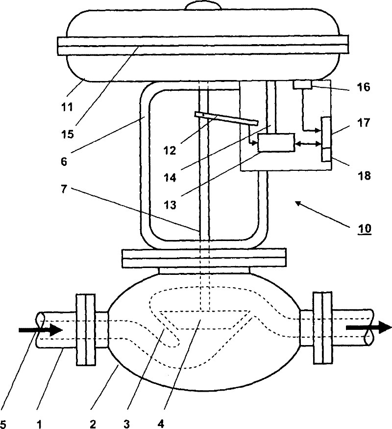
[0025] according to figure 1 , a process valve is arranged in the fragmented line 1 of a process technology device not shown further. The treatment valve has in its interior a closing body 4 which cooperates with the valve seat 3 for controlling the amount of treatment medium 5 flowing through. The closing body 4 is driven linearly by the pneumatic adjustment drive 10 via the lifting rod 7 . The pneumatic adjustment drive 10 is connected to the valve housing 2 of the treatment valve via the yoke 6 . A digital positioner with a positioner 13 is arranged on the yoke 6 . The lift of the lift rod 7 is reported to the position controller area via the position recorder 12 . The detected lift is compared in the positioning controller 13 with a predetermined setpoint value, and the pneumatic actuating drive 10 is actuated as a function of the determined actuating deviation. The pneumatic actuating drive 10 includes a pilot valve arrangement in the area of ​​the positioning control...


PUM


Abstract

The present invention provides a method for determining, through pressure sensing, the working condition of a valve device for controlling and treating a medium flow and a valve device, wherein a control pressure is applied to moving a valve unit (4) which is movably arranged in a valve shell (2) in axial direction, the control pressure applied in the activated and / or inactivated state of the valve unit (4) is measured to determine a static friction; after the valve unit (4) is stopped, a plurality of measurements are performed to determine a pressure increment (delta p) of the control pressure needed by the movement of the valve unit (4); then, the measured pressure increment (delta p)n is temporarily stored in a storage unit (18) and accessed by a diagnosis unit (17) so as to determine, through a statistic analysis, the possible influence on the movement of the valve unit (4) caused by a static friction.

Description

technical field [0001] The invention relates to a method for diagnosing the operating state of a valve device, in particular a pneumatic adjustment drive, for controlling a process medium flow by means of pressure sensing, in which method a valve which is arranged axially displaceable in a valve housing The unit is moved by applying a control pressure, wherein in order to determine the static friction force, the control pressure of the start and / or stop phases of the valve unit is measured. In addition, the invention also relates to a valve device having electronic means for implementing the above-described method. Background technique [0002] The concept "position adjuster" as used in this disclosure supports an electromechanical system that controls an auxiliary energy source of a pneumatic adjustment drive in accordance with one or more input signals in order to bring the valve unit into a specific position. To function, positioning regulation requires gas under pressur...

Claims


Application Information

Patent Timeline
Patent Type & Authority Applications(China)
IPC IPC(8): F15B13/02F15B19/00F16K37/00
CPCF15B19/005F16K37/0075F16K37/0091
Inventor U·E·迈尔D·帕佩
Owner ABB TECH AG
Why Eureka
Try Eureka