
Transmission line transformer and combining and shunting device

A technology for transmission line transformers and branching devices, which is applied in the field of transformers and can solve problems such as branching and combining of information networks in different frequency bands.

Inactive Publication Date: 2012-07-18
北京东方信联科技有限公司
View PDF0 Cites 0 Cited by
  • Summary
  • Abstract
  • Description
  • Claims
  • Application Information

AI Technical Summary

Problems solved by technology

However, in the current combining device and splitting device, such as the existing cavity combiner and microstrip combiner, they cannot satisfy the splitting and combining of the 100KHz-3GHz ultra-wideband multi-channel information network in different frequency bands.

Method used


Image

  • Transmission line transformer and combining and shunting device
  • Transmission line transformer and combining and shunting device
  • Transmission line transformer and combining and shunting device

Examples


Embodiment 1

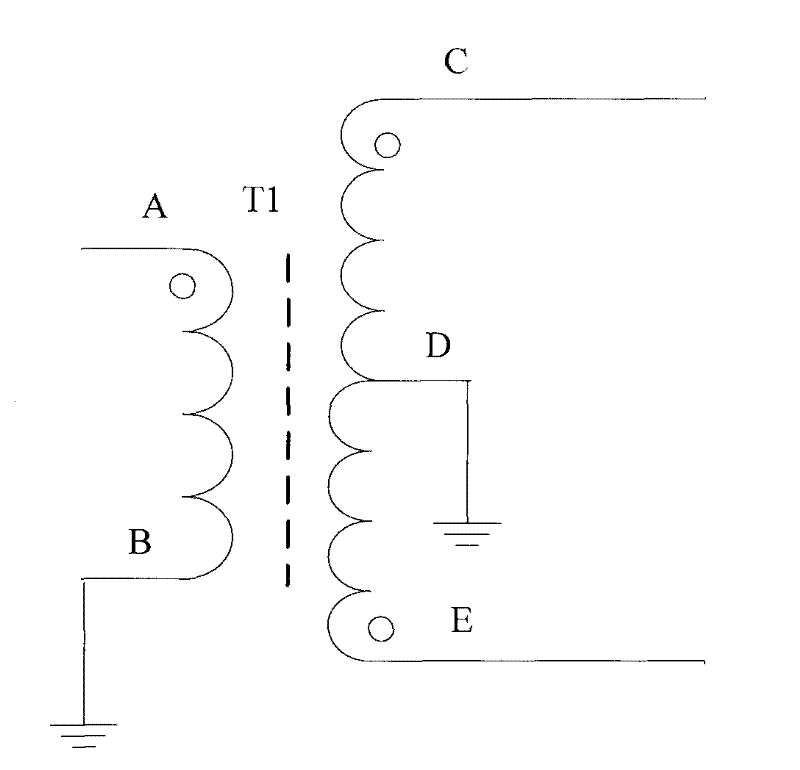
[0032] see figure 1 , which is a schematic diagram of Embodiment 1 of the three-wire 1:1:1 transmission line transformer provided by the present invention.

[0033] The three-wire 1:1:1 transmission line transformer provided in this embodiment includes: a first winding AB, a second winding CD and a third winding ED;

[0034] The number of turns of the first winding AB, the second winding CD and the third winding ED are the same.

[0035] The first winding AB is used as a primary winding; the same-polarity end of the first winding AB is used as a signal input end, and the non-homopolarity end is grounded.

[0036] The second winding CD and the third winding ED are used as secondary windings; the non-homopolar ends of the second winding CD and the non-homopolar ends of the third winding ED are connected and grounded; the second winding Both the same-polarity end of CD and the same-polarity end of the third winding ED serve as signal output ends.

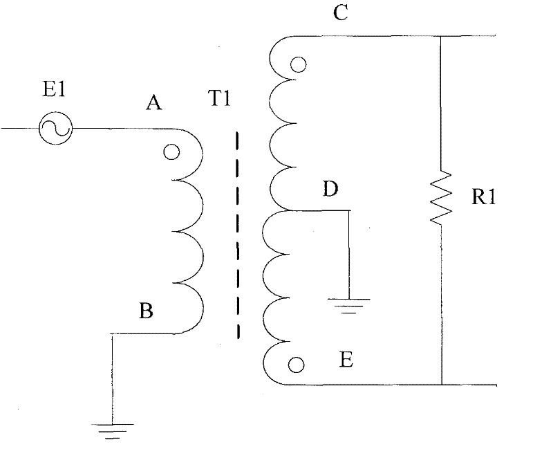
[0037] see figure 2 , when...

Embodiment 2

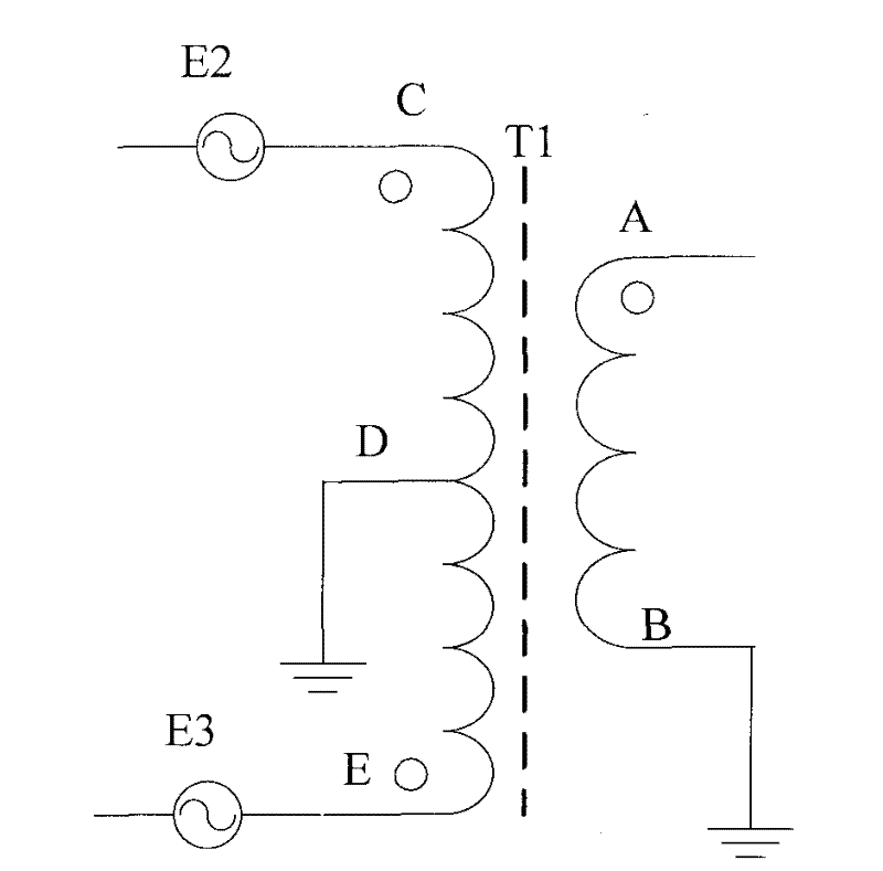
[0044] see image 3 , which is a schematic diagram of Embodiment 2 of the three-wire 1:1:1 transmission line transformer provided by the present invention.

[0045] The three-wire 1:1:1 transmission line transformer provided in this embodiment includes: a first winding AB, a second winding CD and a third winding ED.

[0046] The number of turns of the first winding AB, the second winding CD and the third winding ED are the same.

[0047] The second winding CD and the third winding ED are used as primary windings; the same polarity end of the second winding CD and the same polarity end of the third winding ED are both used as signal input ends; the second winding The non-homopolar ends of the third winding are connected to the non-homopolar ends of the third winding and grounded.

[0048] The first winding AB is used as a secondary winding, and the same-polarity end of the first winding AB is used as a signal output end; the non-homopolarity end of the first winding AB is gro...


PUM


Abstract

The invention provides a transmission line transformer and a combining and shunting device, wherein the transmission line transformer comprises a first winding, a second winding and a third winding; the first winding, the second winding and the third winding have the same number of turns; the first winding serves as a primary winding; a homo-polar end of the first winding serves as a signal inputend, while a non-homo-polar end is grounded; the second winding and the third winding serve as secondary windings; the non-homo-polar end of the second winding and the non-homo-polar end of the thirdwinding are connected with each other and are grounded; and the homo-polar end of the second winding and the homo-polar end of the third winding serve as signal output ends. Because of a structure per se of a three-line 1:1:1 transmission line transformer, the high-frequency response and the electrical conduction property, the transmission line transformer can realize combining and shunting of a super-wide frequency band signal of between 100 KHz and 3 GHz.

Description

technical field [0001] The invention relates to the technical field of transformers, in particular to a transmission line transformer and a circuit combining and branching device. Background technique [0002] At present, in the construction of the resident access network, many occasions require multiple public information networks to be transmitted on the same cable or the same optical fiber. However, in the current combining devices and splitting devices, such as the existing cavity combiner and microstrip combiner, they cannot satisfy the splitting and combining of multi-channel information networks in different frequency bands with an ultra-wide frequency band of 100KHz-3GHz. Contents of the invention [0003] The technical problem to be solved by the present invention is to use a three-wire 1:1:1 transmission line transformer to realize the branching and combining of various signals. [0004] An embodiment of the present invention provides a branching device, includi...

Claims


Application Information

Patent Timeline
Patent Type & Authority Patents(China)
IPC IPC(8): H01F27/28H01F27/40
Inventor 繆赢韩大庆徐罕聪
Owner 北京东方信联科技有限公司
Learn More