
Poppet valve operated by an electrohydraulic poppet pilot valve

An electric and hydraulic technology, applied in the direction of valve operation/release device, lift valve, valve device, etc., can solve the problems of enlargement, precise control of adverse effects, short stroke, etc.

Active Publication Date: 2010-06-30
HUSCO INT INC
View PDF5 Cites 20 Cited by
  • Summary
  • Abstract
  • Description
  • Claims
  • Application Information

AI Technical Summary

Problems solved by technology

Another disadvantage: the stroke of the poppet is shorter than the stroke of the solenoid
This valve design is relatively fast and proportional, but due to the high flow in the control chamber through the relatively large control passage orifice, additional pressure compensators are required to oversize the valve to the larger size of
In addition, increasing the control orifice introduces a non-linear relationship between fluid pressure and flow and the current applied to the solenoid, which can adversely affect precise control

Method used


Image

  • Poppet valve operated by an electrohydraulic poppet pilot valve
  • Poppet valve operated by an electrohydraulic poppet pilot valve
  • Poppet valve operated by an electrohydraulic poppet pilot valve

Examples


Embodiment Construction

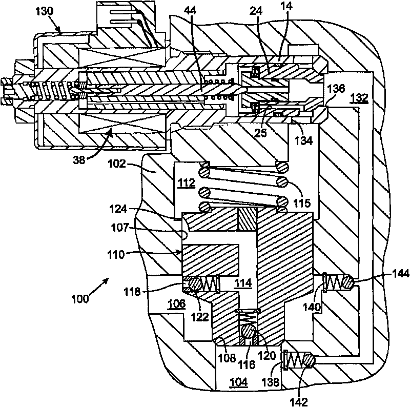
[0019] see first figure 1 , the two-way control valve 100 has a body 102 with a first port 104 and a second port 106 opening to a main hole 107 . The valve seat 108 is located between the first and second ports 104 and 106 . The main poppet 110 is slidably received in the body 102 and selectively cooperates with the valve seat 108 to close the fluid path between the first and second ports 104 and 106 . The main poppet 110 is slidable from engagement with the valve seat 108 to open the flow path between the first and second ports 104 and 106 . As will be described in more detail below, the movement of the main poppet is controlled by the main spring 115 and the main control chamber 112 in the first and second ports 104 and 106 connected to the side of the main poppet 110 away from the valve seat 108. Determined by the pressure relationship in the

[0020] The main poppet 110 has a passageway 114 with a first opening 116 into the first port 104 and a second opening 118 into t...


PUM


Abstract

A control valve includes a main poppet that moves in response to pressure in a primary control chamber and thereby controls the flow of fluid through a valve seat between first and second ports. A passageway extends between the second port and the primary control chamber and includes a variable flow restriction that decreases as the main poppet moves away from the valve seat. An electrohydraulic pilot valve has a pilot poppet which controls fluid flow from the primary control chamber to the first port in response to pressure in a pilot control chamber. A sub-pilot valve selectively releases pressure in the pilot control chamber to operate the pilot poppet to open and close a path between the inlet and the outlet. Using an electrohydraulic pilot valve enables the main poppet to operate quickly in controlling large fluid flow rates. Unidirectional and bidirectional versions of the control valve are described.

Description

technical field [0001] This invention relates to hydraulically operated pilot valves, and more particularly to electric pilot valves. Background technique [0002] Many machines have movable parts operated by hydraulic actuators, such as hydraulic cylinders and piston arrangements, controlled by hydraulic valves. Traditionally, hydraulic valves are manually operated by machine operators. The current trend is to move away from manually operated hydraulic valves to electrically controlled and solenoid valves. [0003] As shown in U.S. Patent No. 6,149,124, the application of hydraulic fluid from the pump to the actuator is controlled by metering the flow of fluid into and out of the hydraulic cylinder through a set of proportional pilot-operated control valves placed in a Wheatstone bridge. apply. Each control valve has a poppet that engages and disengages the valve seat to control fluid flow between the inlet and outlet of the valve. A control chamber is formed on a side ...

Claims


Application Information

Patent Timeline
Patent Type & Authority Applications(China)
IPC IPC(8): F16K1/00F16K31/06F16K31/40
CPCF15B13/0405F16K31/406F15B13/0433Y10T137/7764
Inventor J·L·普法弗
Owner HUSCO INT INC
Learn More