
Light angular sensor

A light angle and sensor technology, applied in the field of sensors, can solve problems such as high cost and complex structure

Inactive Publication Date: 2010-06-30
SHANGHAI QIBAO HIGH SCHOOL
View PDF0 Cites 6 Cited by
  • Summary
  • Abstract
  • Description
  • Claims
  • Application Information

AI Technical Summary

Problems solved by technology

Therefore, some people have invented light angle sensing for use with solar installations, but these light angle sensors are usually complex and expensive
There is no light angle sensor with simple structure, low cost and good precision on the market now.

Method used


Image

  • Light angular sensor
  • Light angular sensor
  • Light angular sensor

Examples


Embodiment Construction

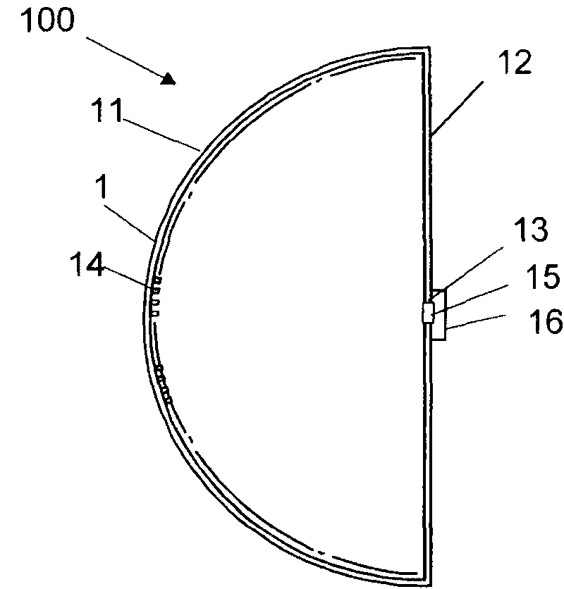
[0018] Such as figure 1 As shown, the light angle sensor 100 of the present invention includes a light-tight hemispherical housing 1, and the hemispherical housing 1 is surrounded by a hemispherical surface 11 and a circular flat surface 12. There is a light-transmitting hole 13 in the center of the circular plane 12, that is, the axis of symmetry of the half-shaped shell 1, and the inner surface of the hemispherical surface 11 is densely covered with photosensitive elements 14. The photosensitive elements 14 may be photodiodes or phototransistors. Or other photosensitive elements.

[0019] In order to avoid refraction of the light entering the hemispherical housing 1 and to keep the angle of the light entering the hemispherical housing as consistent as possible with the outside world, the light-transmitting hole 11 is provided with a light-transmitting sheet 15, and the hemispherical housing 1 is drawn Into a vacuum.

[0020] In order to ensure that the light angle sensor senses ...


PUM


Abstract

The invention relates to a light angular sensor, comprising a light proof hemispherical casing enclosed by a hemispherical surface and a round plane. The symmetrical axis position of the hemispherical casing is provided with a light hole, and the inner surface of the hemispherical surface of the hemispherical casing is densely covered with photosensitive elements. The light angular sensor has the advantages of simple structure, low cost and capability of accurately measuring the light angle.

Description

Technical field [0001] The invention relates to a sensor, in particular to a light angle sensor. Background technique [0002] The sun is a precious resource that humans can make unlimited use. With the development of science and technology, the use of solar energy is deepening. However, the light emitted by the sun has an angle, and the angle is constantly changing, which requires consideration of the change in the angle of the light when using solar energy, so as to improve the utilization efficiency of solar energy. Therefore, some people have invented light angle sensors for use with solar devices, but these light angle sensors are usually complex in structure and expensive. Currently, there is no light angle sensor with simple structure, low cost and good accuracy on the market. Summary of the invention [0003] The technical problem to be solved by the present invention is to provide a light angle sensor with simple structure, low cost and excellent accuracy. [0004] In o...

Claims


Application Information

Patent Timeline
IPC IPC(8): G01C1/00
Inventor 王雪岚潜龙昊
Owner SHANGHAI QIBAO HIGH SCHOOL
Learn More