Micro heating disk and manufacturing method thereof as well as micro heating disk system

A production method and micro-heating technology, applied in the field of sensors, can solve the problems of aging drift of the temperature sensing unit material, and achieve the effects of low cost, high precision, and increased contact area

Inactive Publication Date: 2018-06-29
武汉微纳传感技术有限公司
View PDF2 Cites 5 Cited by
  • Summary
  • Abstract
  • Description
  • Claims
  • Application Information

AI Technical Summary

Problems solved by technology

In practical applications, this solution is exposed to high temperature for a lon

Method used


Image

  • Micro heating disk and manufacturing method thereof as well as micro heating disk system
  • Micro heating disk and manufacturing method thereof as well as micro heating disk system
  • Micro heating disk and manufacturing method thereof as well as micro heating disk system

Examples


Embodiment 1

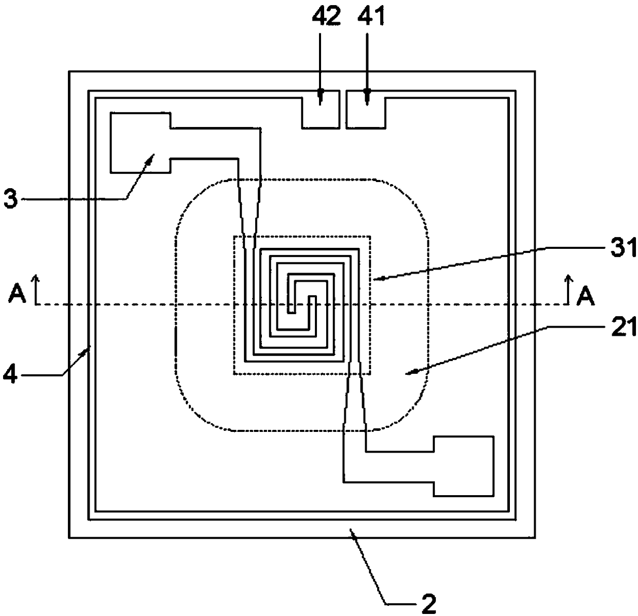
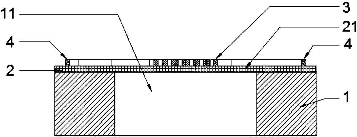
[0036] A micro hot plate, such as figure 1 with figure 2 As shown, it includes: a substrate 1, an insulating support layer 2 and a resistance heating layer 3 stacked sequentially from bottom to top, a temperature isolation cavity 11 is provided in the middle of the substrate 1, and the insulation support layer on the upper part of the temperature isolation cavity 11 2 is the temperature isolation suspension film 21, the resistance heating layer 3 is located on the insulating support layer 2 in a preset shape, the heating area 31 of the resistance heating layer 3 is located in the middle of the temperature isolation suspension film 21, and also includes a temperature sensing unit 4, the temperature sensor The measurement unit 4 is arranged around the substrate 1 (that is, the micro hot plate chip) in a ring shape.

[0037] By using the annular temperature sensing unit arranged around the substrate, the contact area between the temperature sensing unit and the environment is i...

Embodiment 2

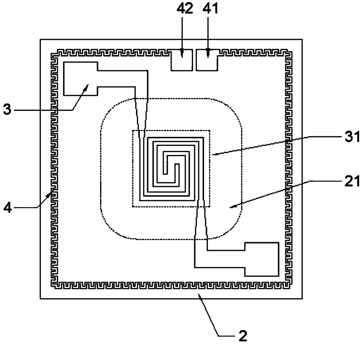
[0050] A micro hot plate, such as image 3 As shown, it includes: a substrate 1, an insulating support layer 2 and a resistance heating layer 3 stacked sequentially from bottom to top, a temperature isolation cavity 11 is provided in the middle of the substrate 1, and the insulation support layer on the upper part of the temperature isolation cavity 11 2 is the temperature isolation suspension film 21, the resistance heating layer 3 is located on the insulating support layer 2 in a preset shape, the heating area 31 of the resistance heating layer 3 is located in the middle of the temperature isolation suspension film 21, and also includes a temperature sensing unit 4, the temperature sensor The measurement unit 4 is arranged around the substrate 1 (that is, the micro hot plate chip) in a ring shape.

[0051] By adopting the annular temperature sensing unit arranged around the chip, the contact area between the temperature sensing unit and the environment is increased, and the ...

Embodiment 3

[0065] A micro hot plate, such as Figure 4 As shown, it includes: a substrate 1, an insulating support layer 2 and a resistance heating layer 3 stacked sequentially from bottom to top, a temperature isolation cavity 11 is provided in the middle of the substrate 1, and the insulation support layer on the upper part of the temperature isolation cavity 11 2 is the temperature isolation suspension film 21, the resistance heating layer 3 is located on the insulating support layer 2 in a preset shape, the heating area 31 of the resistance heating layer 3 is located in the middle of the temperature isolation suspension film 21, and also includes a temperature sensing unit 4, the temperature sensor The measurement unit 4 is arranged around the substrate 1 (that is, the micro hot plate chip) in a ring shape.

[0066] By adopting the annular temperature sensing unit arranged around the chip, the contact area between the temperature sensing unit and the environment is increased, and the...


PUM


Abstract

The invention relates to a micro heating disk and a manufacturing method thereof as well as a micro heating disk system. The micro heating disk comprises a substrate, an insulating supporting layer, aresistance heating layer and a temperature sensing unit, wherein the annular temperature sensing unit is arranged at the periphery of the substrate. According to the micro heating disk disclosed by the invention, by the arrangement of the annular temperature sensing unit arranged at the periphery, a contact area of the temperature sensing unit and the environment is enlarged, and the accuracy ofsensed ambient temperature is high; the temperature sensing unit works at room temperature, so that the long-term stability is high; meanwhile, an annular metal layer can effectively shield the influence of external electromagnetic interference on the work of a micro heating disk chip; furthermore, the temperature sensing unit can precisely sense a temperature change of a surrounding environment in real time and automatically transmit the acquired temperature to control heating power of a heating region to stabilize the working temperature of the chip; the micro heating disk is convenient andquick.

Description

technical field [0001] The invention relates to the technical field of sensors, in particular to a micro-hot plate, a manufacturing method thereof, and a micro-hot plate system. Background technique [0002] Micro hot plate devices are widely used in products that require local high temperature, including high temperature chemical sensors, micro chemical reactors, infrared light sources, flow sensors, etc. [0003] The micro-thermal plate achieves small size and low power consumption through temperature isolation technology. When the micro-hot plate is working, the actual working temperature of the heating area has an important influence on the application of the product. Specific to the application fields of chemical sensing and chemical reactors, temperature conditions directly affect the activity and chemical reaction speed of sensing materials; when the micro-hot plate is used as an NDIR infrared light source, the emission efficiency of the infrared light source is prop...

Claims


Application Information

Patent Timeline
IPC IPC(8): H05B3/12H05B3/02H05B1/02
CPCH05B1/02H05B3/02H05B3/12
Inventor 雷鸣饶吉磊贺方杰
Owner 武汉微纳传感技术有限公司
Why Eureka
Try Eureka