Apparatus for heat exchange with radial mixing

An equipment, axial technology, applied in the field of equipment using radial mixing for heat exchange, which can solve the problem of peak loads on shafts and drives

Inactive Publication Date: 2010-06-30
高达机械工厂有限公司
View PDF1 Cites 11 Cited by
  • Summary
  • Abstract
  • Description
  • Claims
  • Application Information

AI Technical Summary

Problems solved by technology

A disadvantage of this arrangement is that...

Method used


Image

  • Apparatus for heat exchange with radial mixing
  • Apparatus for heat exchange with radial mixing
  • Apparatus for heat exchange with radial mixing

Examples


Embodiment Construction

[0018] It should be noted that the drawings are merely schematic illustrations of preferred embodiments of the invention, which are described by way of non-limiting exemplary embodiments. In the drawings, the same or corresponding parts are denoted by the same reference numerals.

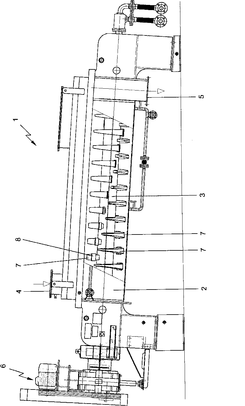
[0019] figure 1 A device 1 comprising a tank 2 is shown. exist figure 1 In , slot 2 is partially cut away so that shaft 3 can be seen. The slot 2 comprises two rotatably arranged shafts 3 extending alongside each other. The device 1 is provided with an inlet 4 along which the product to be processed is supplied into the tank 2 and an outlet 5 from which the product is discharged. The shaft 3 is arranged along a direction corresponding to the path between the inlet 4 and the outlet 5 of the tank 2 . Shaft 3 is driven by drive 6 .

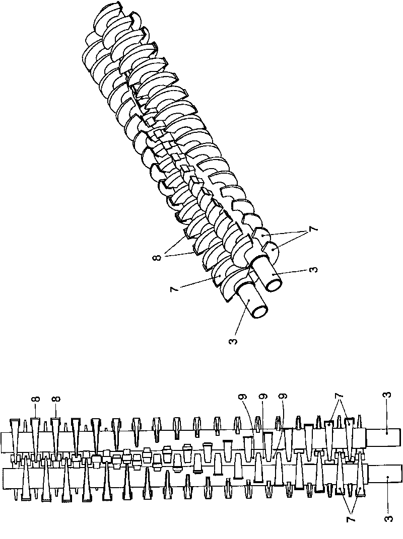
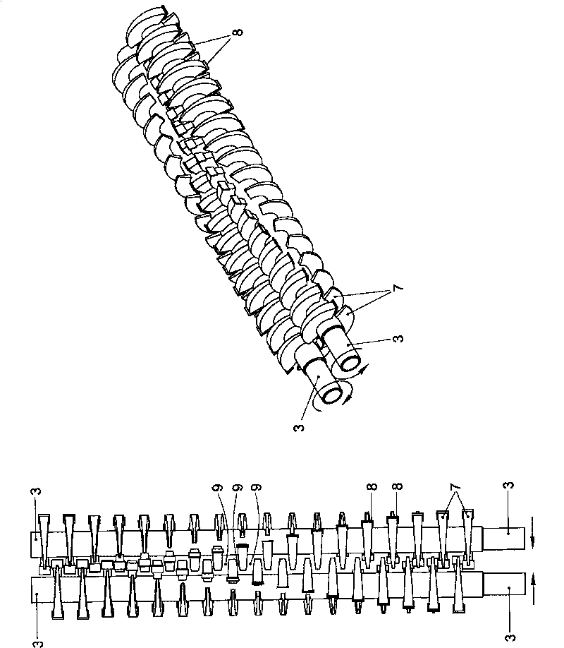
[0020] The shaft 3 is provided with blades 7 spaced axially at a moderate distance, and the blades 7 are arranged in a helical form, such as figure 1 shown. The bl...


PUM


Abstract

Apparatus (1) comprises a trough(2) with two rotatably arranged shafts (3) extending alongside each other, which shafts (3) are each provided with paddles (7) spaced apart in axial direction with an intermediate distance. The paddles (7) extend substantially in a radial plane with respect to the shafts (3) and extend in circumferential direction over at least a part of the circumference. In circumferential direction, the paddles (7) are at least partly wedge-shaped. Upon opposite rotation of the shafts (3), successive paddles (7) mesh alternately, thereby forming a gap narrowing again and again. Per shaft (3), successive paddles (7) in axial direction are staggered relative to each other in circumferential direction through an angle.

Description

technical field [0001] The present invention relates to a device comprising a trough having two rotatably arranged shafts extending side by side, each shaft being provided with blades axially spaced at a moderate distance, the blades extending substantially radially relative to the shaft. Extending planarly, extending circumferentially over at least a portion of the circumference, and being at least partially wedge-shaped circumferentially, successive vanes in the axial direction alternately engage as the shaft counter-rotates, thereby forming repeatedly narrowing gaps , the gap has no axial pitch. Background technique [0002] Such devices are generally known. One structure is described, for example, in JP 58117954 in the name of Nara Machinery Company Ltd. In this device, since there is no axial pitch in the gap, the product is mixed approximately radially when substantially no force is applied axially. The conveying in the axial direction is not carried out by the vane...

Claims


Application Information

Patent Timeline
IPC IPC(8): F28F5/04
CPCB01F7/042F28F5/04F26B17/20B01F7/021B01F7/00425B01F15/068B01F27/1144B01F27/61B01F27/702B01F35/95
Inventor U·M·范艾尔德恩T·G·拉文斯伯格R·J·M·范海杰因根
Owner 高达机械工厂有限公司
Why Eureka
Try Eureka