Reciprocating high-efficiency vortex fluid magnetizer

A fluid magnetizer, reciprocating technology, applied in the direction of machines/engines, internal combustion piston engines, engine components, etc., can solve the problem of no fuel-saving effect, achieve enhanced magnetic field strength and magnetization effect, prolong magnetization and magnetization time, prolong Effect of Magnetization Time

Active Publication Date: 2012-06-20
王跃进
View PDF0 Cites 0 Cited by
  • Summary
  • Abstract
  • Description
  • Claims
  • Application Information

AI Technical Summary

Problems solved by technology

[0002] At present, the magnetization process of traditional gasoline or diesel magnetizers on the market is mostly completed in a constant magnetic field, so this type of magnetizer (also called fuel-saving device) basically has no obvious fuel-saving effect

Method used


Image

  • Reciprocating high-efficiency vortex fluid magnetizer
  • Reciprocating high-efficiency vortex fluid magnetizer
  • Reciprocating high-efficiency vortex fluid magnetizer

Examples


Embodiment 1

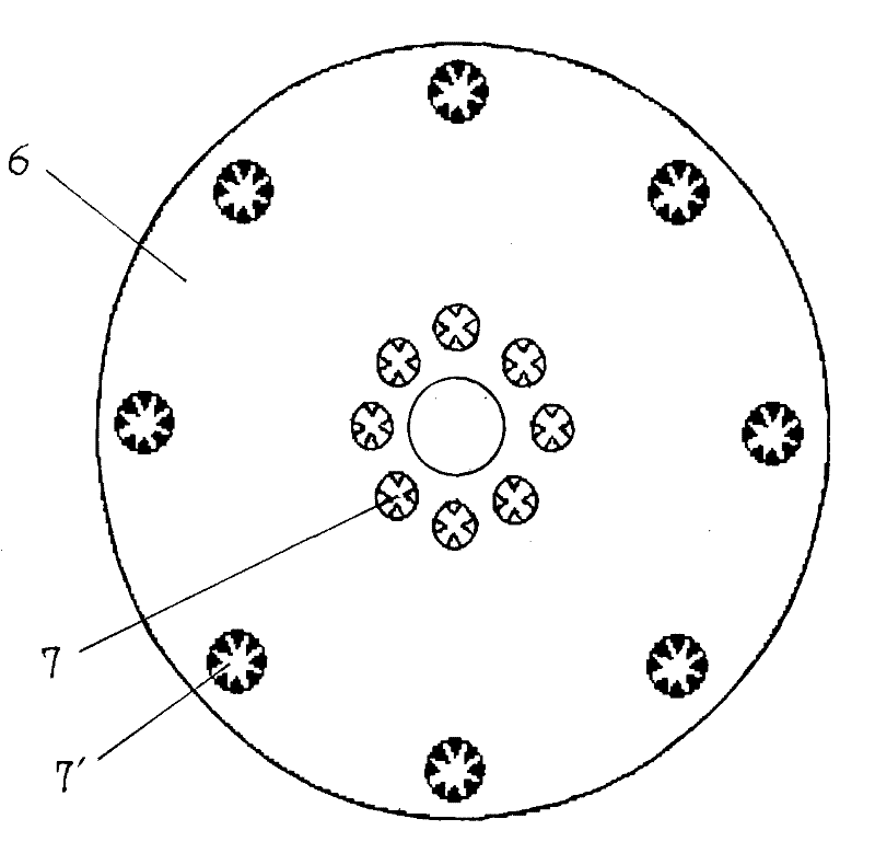
[0027] Such as figure 1 As shown, the housing 8 is in the shape of a cylinder made of a non-magnetic material, and the butt joints can be screwed together as required, or closed and welded. The liquid inlet pipe 1 is connected to the center of the top surface of the housing 8 . Four ring magnets 5 (which can be increased by 2) are arranged in the housing 8 . The upper and lower positions of the ring magnets 5 are relatively overlapped, and the magnetic ring planes of the same polarity are opposite to each other. Considering the problem of installation space, the volume of the magnetizer should not be too large, and generally 4 or 6 ring magnets are suitable. A magnetic short-circuit piece 6 is respectively arranged on the magnetic ring plane of the ring magnet, and an upper positioning piece 12 and a lower positioning piece 13 are respectively arranged on the top surface of the upper layer ring magnet and the bottom surface of the lower layer ring magnet. The magnetic short ...

Embodiment 2

[0035] This embodiment is a magnetizer with double magnetizer structure. Such as Figure 5 As shown, two parallel magnetized bodies are housed in a housing 8 with an approximately elliptical cross section, and each magnetized body is composed of a ring magnet 5, a magnetic short circuit 6, an isolation deflector 3, and a current guide as described in the above example. Pipe 9, isolation cover 2, upper positioning piece 12 and lower positioning piece 13 etc. are connected and formed. A mediastinum 19 separating the two magnetized bodies is provided between the two magnetized bodies, and the upper positioning piece 12 and the lower positioning piece 13 of the two magnetized bodies are respectively fixedly connected to the mediastinum plate 19 . The isolation cover 2 in each magnetized body is arranged on the upper positioning piece 12 , and the top surface of each isolation cover 2 is provided with a support block 27 fixedly connected with the top surface of the housing 8 . Th...

Embodiment 3

[0038] This embodiment is another magnetizer with double magnetizer structure. Such as Figure 6 As shown, the housing 8 is also a cylindrical structure with an approximately elliptical cross section, and two parallel magnetized bodies are housed in the housing 8, and each magnetized body is composed of a ring magnet 5, a magnetic short circuit piece 6, an isolation guide Device 3, guide pipe 9 and isolation cover 2 etc. are connected by the structural mode in embodiment 1 and form. In this embodiment, the two magnetized bodies share an upper positioning piece 12 and a lower positioning piece 13, and the two isolation covers 2 are all arranged on the upper positioning piece 12, and a medial septum 19 is arranged between the two magnetized bodies. The two magnetized bodies are isolated from each other.

[0039] Figure 6 Among them, the left side in the housing 8 is the first magnetized body, and the right side is the second magnetized body. The upper end of the guide tube ...


PUM


Abstract

The invention relates to a reciprocating high-efficiency vortex fluid magnetizer. The structure of the fluid magnetizer is that: a magnetizer which is formed by connecting annular magnets, a magnetic short circuit bar, an isolating fluid director, a flow guide pipe, an isolating cap, upper and lower positioning plates and the like is arranged in a shell; four or more even annular magnets are provided; a vortex screw bar is inserted into the flow guide pipe; and a magnetic or magnetic conductive mandrel is inserted into the vortex screw bar. Most of originally diffused magnetic lines in a magnetizer device are centralized inside the device, so the magnetic flux is increased and the magnetizing effect is remarkably improved. The magnetizer has various magnetizing forms, such as reciprocating, alternating and vortex and other forms, so the magnetizer has full magnetization and good effect. The fluid magnetizer is suitable for magnetizing fuel oil of motor vehicles, drinking water, medical water and fuel gas and can be used for magnetizing a motor vehicle water cooling system, an air compressor cooling system and warming water for a boiler.

Description

technical field [0001] The invention relates to a device for processing fuel by a magnetic method, in particular to a reciprocating high-efficiency eddy current fluid magnetizer. Background technique [0002] The magnetization process of traditional gasoline or diesel magnetizers currently on the market is mostly completed in a constant magnetic field, so this type of magnetizer (also called a fuel-saving device) basically has no obvious fuel-saving effect. my country's National Motor Vehicle Product Quality Supervision and Inspection Center has conducted testing experiments on many fuel-saving products for motor vehicles, and the result of the experiment is that "no fuel-saving products have been found to have obvious fuel-saving effects." Contents of the invention [0003] The object of the present invention is to provide a reciprocating high-efficiency eddy current fluid magnetizer with obvious fuel-saving effect, so as to realize the fuel-saving purpose of motor vehicl...

Claims


Application Information

Patent Timeline
Patent Type & Authority Patents(China)
IPC IPC(8): F02M27/04
CPCY02T10/126Y02T10/12
Inventor 王鹏玮王跃进
Owner 王跃进
Why Eureka
Try Eureka