Magnetic rod antenna

A magnetic rod antenna, the technology of the magnetic rod, which is applied in the direction of the loop antenna with a ferromagnetic material core, etc., can solve the problems of the limited signal transmission distance of the magnetic rod antenna and being easily interfered by the external environment.

Inactive Publication Date: 2016-06-29
仓领电子科技(上海)有限公司
View PDF3 Cites 7 Cited by
  • Summary
  • Abstract
  • Description
  • Claims
  • Application Information

AI Technical Summary

Problems solved by technology

[0004] In view of this, the present invention provides a magnetic rod antenna to improve the shortcomings of the existing mag

Method used


Image

  • Magnetic rod antenna
  • Magnetic rod antenna

Examples


Embodiment Construction

[0034] The technical solutions in the embodiments of the present invention will be clearly and completely described below in conjunction with the accompanying drawings in the embodiments of the present invention. Apparently, the described embodiments are only some of the embodiments of the present invention, but not all of them. The following detailed description of the embodiments of the invention provided in the accompanying drawings is not intended to limit the scope of the claimed invention, but merely represents selected embodiments of the invention. Based on the embodiments of the present invention, all other embodiments obtained by those skilled in the art without making creative efforts belong to the protection scope of the present invention.

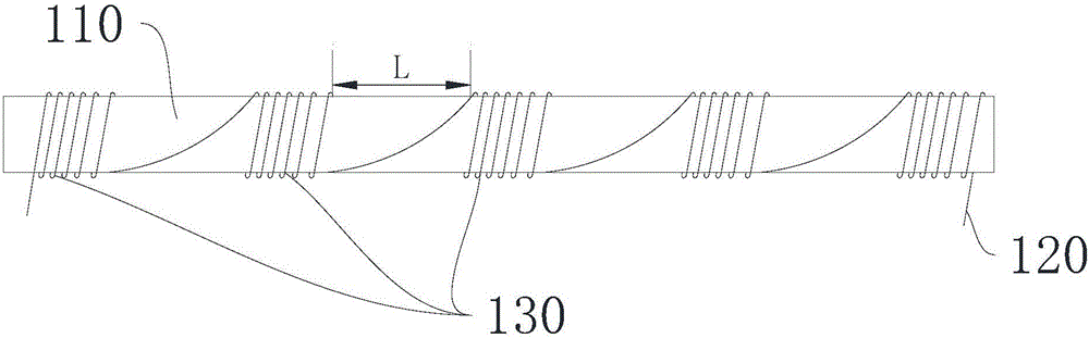
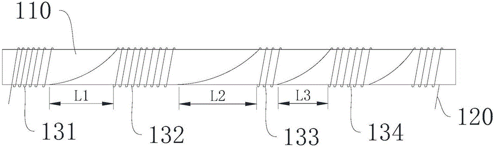
[0035] See figure 1 , figure 1 A magnetic rod antenna provided by the first embodiment of the present invention is shown. The bar magnet antenna includes a bar magnet 110 and a wire 120 , and multiple parts of the wire 120 ar...


PUM

PropertyMeasurementUnit
Diameteraaaaaaaaaa

Abstract

The invention provides a magnetic rod antenna. The magnetic rod antenna comprises a magnetic rod and a wire, wherein a plurality of parts of the wire are sequentially wound around the magnetic rod to form a plurality of coils in an alternately sparse and dense manner, and the magnetic field intensity of the plurality of coils laminated on division magnetic fields of respective cross section of the same magnetic rod is higher than the magnetic field intensity of the total magnetic field of the coil formed by uniformly winding the existing wire around the magnetic rod. The magnetic rod antenna provided by the invention is longer in signal transmission distance, and is not susceptible to the interference of an outside environment; and moreover, with the magnetic rod antenna provided by the invention, the magnetic flux of the antenna can be improved.

Description

technical field [0001] The present invention relates to the technical field of antennas, in particular to a magnetic rod antenna. Background technique [0002] In engineering construction, it is often necessary to penetrate the ground to transmit the collected signals from the ground to the surface through wireless transmission, and then restore and analyze them through surface instruments such as handheld instruments. [0003] In modern communication technologies, WiFi, Bluetooth, ZigBee, etc. cannot be used because they cannot penetrate thick barrier layers. The traditional 1k ~ 100kHz electromagnetic wave is easier to penetrate the formation when it is emitted by a magnetic rod antenna, but its penetration distance is limited and it is easily disturbed by the external environment. With the acceleration of urbanization and the complexity of pipe network layout, trenchless construction has expanded from the initial 10 meters underground to 20 to 30 meters. Therefore, ther...

Claims


Application Information

Patent Timeline
IPC IPC(8): H01Q7/08
CPCH01Q7/08
Inventor 沈培林邓武仓
Owner 仓领电子科技(上海)有限公司
Why Eureka
Try Eureka