
Multi-camera synchronous triggering system

A synchronous triggering, multi-camera technology, applied in the field of communication, can solve the problems of increased system cost and complexity, difficulty in meeting the system synchronous triggering and taking pictures, etc., to achieve the effect of improving system flexibility and no time delay

Inactive Publication Date: 2020-04-10
易思维(杭州)科技有限公司
View PDF8 Cites 4 Cited by
  • Summary
  • Abstract
  • Description
  • Claims
  • Application Information

AI Technical Summary

Problems solved by technology

[0003] 1. Soft trigger mode, that is, the trigger command is sent to each camera one by one through the host computer software. Due to the time sequence of the execution of the software trigger commands of each camera, coupled with the influence of the uncertainty of the operating system scheduling, each camera receives The delay of the trigger command reaches tens of milliseconds, which is difficult to meet the requirements of the system to trigger the camera synchronously;
[0004] 2. In the hard trigger mode, each camera is connected to a trigger signal line to a trigger signal source. When there are many cameras that need to be triggered at the same time in the system, the cost and complexity of the system will increase greatly;
[0005] 3. Network broadcast command mode, this solution is only for interface cameras with network communication, and industrial cameras have multiple interface standards, if the camera is not a network interface, it needs to lay a special network for triggering, and requires additional equipment support

Method used


Image

  • Multi-camera synchronous triggering system
  • Multi-camera synchronous triggering system
  • Multi-camera synchronous triggering system

Examples


Embodiment Construction

[0030] The technical solution of the present invention is described in detail in conjunction with the drawings and specific embodiments.

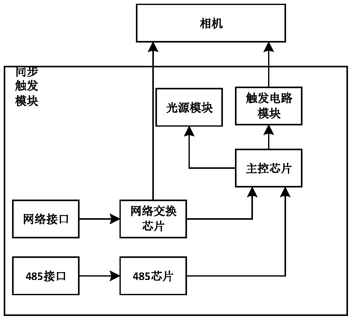
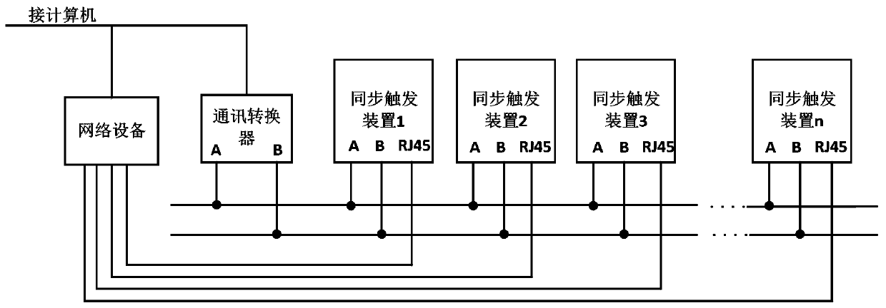
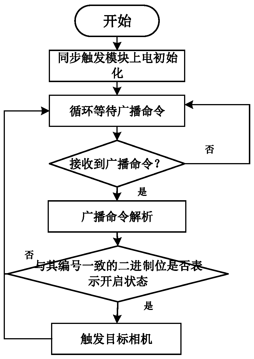
[0031] A multi-camera synchronous trigger system, such as figure 1 As shown, it includes multiple synchronous trigger modules, and each synchronous trigger module is connected to the camera to be triggered; the synchronous trigger module includes a main control chip, a communication module and a trigger module, and the communication module and the trigger module are respectively connected to the main control chip; the communication module receives the upper The command data packet sent by the camera is transmitted to the main control chip, and the main control chip parses the command data packet and judges whether to send a trigger signal to the trigger module according to the parsed command data; the trigger module is connected with the camera, when it receives the trigger After the signal (GPIO signal), trigger the camera to start capturi...


PUM


Abstract

The invention discloses a multi-camera synchronous triggering system, which comprises a plurality of synchronous triggering modules. Each synchronous triggering module is connected with a to-be-triggered camera; the synchronous triggering module comprises a main control chip, a communication module and a triggering module, and the communication module and the triggering module are respectively connected with the main control chip; the communication module receives an instruction data packet sent by an upper computer and transmits the instruction data packet to the main control chip, and the main control chip analyzes the instruction data packet and judges whether to send a triggering signal to the triggering module or not according to the analyzed instruction data; the triggering module isconnected with the camera, and triggers the camera to start to collect images after receiving the triggering signal. According to the technical scheme, any multiple cameras can be triggered synchronously, scheduling of an operating system is not needed, time delay is avoided, the real-time performance is high, two triggering channels of a network broadcast triggering mode and an RS485 triggeringmode are designed, and the flexibility of the system is improved; therefore, the system can be suitable for a camera with a network interface and can also be compatible with a camera without a networkinterface.

Description

technical field [0001] The invention relates to the communication field, in particular to a multi-camera synchronous triggering system. Background technique [0002] In the field of machine vision inspection, all cameras in the system or multiple cameras in the system need to be triggered to take pictures at the same time. The existing technology mainly adopts the following methods: [0003] 1. Soft trigger mode, that is, the trigger command is sent to each camera one by one through the host computer software. Due to the time sequence of the software trigger command execution of each camera, coupled with the influence of the uncertainty of the operating system scheduling, each camera receives The delay of the trigger command reaches tens of milliseconds, which is difficult to meet the requirements of the system to trigger the camera synchronously; [0004] 2. In the hard trigger mode, each camera is connected to a trigger signal line and a trigger signal source. When there ...

Claims


Application Information

Patent Timeline
IPC IPC(8): H04N5/232
CPCH04N23/66H04N23/60
Inventor 张乃华傅灵忠秦凤滨吕猛
Owner 易思维(杭州)科技有限公司
Learn More