

Ring type sintered magnet
A sintered magnet, ring-shaped technology, applied in the direction of magnetic circuit, magnetic circuit shape/style/structure, magnetic material, etc., can solve problems such as poor shape accuracy, reduce motor current, increase torque, and reduce unevenness Effect
- Summary
- Abstract
- Description
- Claims
- Application Information
AI Technical Summary
Problems solved by technology
Method used
Image

Examples
Embodiment approach 1
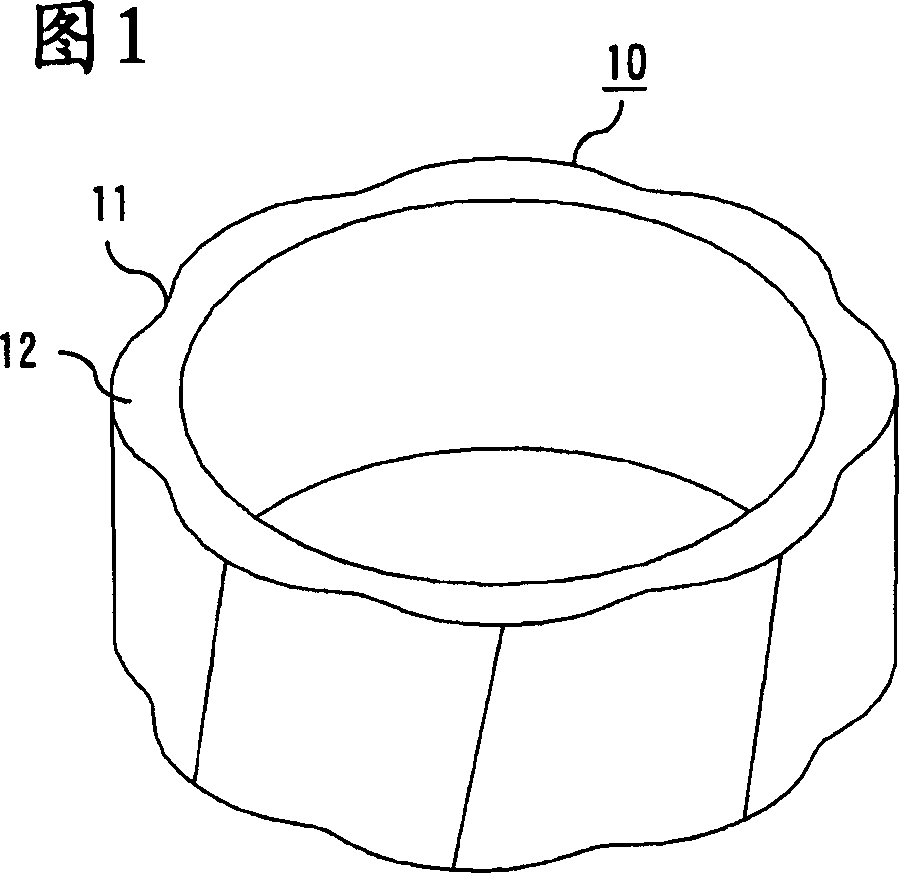
[0059] FIG. 1 is a perspective view showing an annular sintered magnet according to Embodiment 1 of the present invention. The magnet 10 according to this embodiment is a ring-shaped sintered magnet mainly composed of neodymium (Nd), iron (Fe), and boron (B). The recesses 11 and protrusions 12 are periodically formed in the outer diameter circumferential direction of the annular sintered magnet 10 . In the ring-shaped sintered magnet of FIG. 1 , eight recesses 11 and protrusions 12 are provided at predetermined angular intervals (45-degree intervals), respectively.
[0060] The uneven shape is formed by rotating and twisting at a predetermined angle with respect to the axial direction of the ring magnet 10 . In addition, the magnetic poles of the ring-shaped sintered magnet 10 are formed by rotating and twisting at a predetermined angle with respect to the axial direction along the above-mentioned concavo-convex shape, and are usually twisted and magnetized. Furthermore, the...
Embodiment approach 2
[0069] The ring-shaped sintered magnet of this embodiment is the same as that of Embodiment 1. It is a ring-shaped sintered magnet mainly composed of neodymium, iron, and boron, and has a concave-convex shape on the outer periphery of the ring. The concavo-convex shape is formed by rotating and twisting at a predetermined angle with respect to the axial direction. In addition, the magnetic poles of the magnet are formed along the concavo-convex shape, and the boundaries of the magnetic poles are provided in the concave portions. This embodiment is characterized in that the outermost periphery of the convex shape of the outer diameter of the magnet is constituted by a part (arc) of a circle centered on the center of the inner diameter of the ring, that is, the rotating shaft.
[0070] The ring-shaped sintered magnet of this embodiment is manufactured by a powder sintering method in which a magnetic field is applied to magnetic powder, compression-molded, and then sintered and h...
Embodiment approach 3
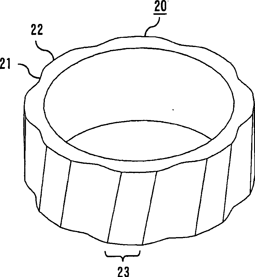
[0074] figure 2 It is a perspective view showing the annular sintered magnet according to Embodiment 3 of the present invention. The ring-shaped sintered magnet 20 of this embodiment is the same as the first embodiment, and is a sintered magnet mainly composed of neodymium, iron, and boron. The concavo-convex shape is formed by rotating and twisting at a predetermined angle with respect to the axial direction.
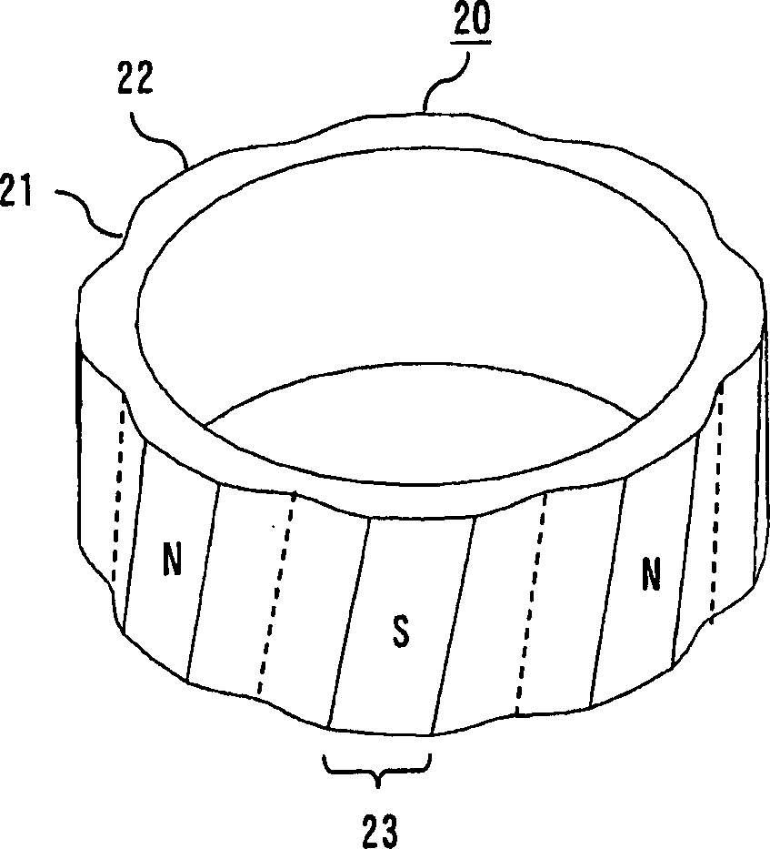
[0075] Additionally, if image 3 As shown, the magnetic poles of the ring-shaped sintered magnet 20 are formed by rotating and twisting at a predetermined angle with respect to the axial direction along the concave-convex shape. Magnetic pole boundaries (shown by dotted lines in the figure) are disposed in the concave portion 21 . In addition, all the protrusions 22 on the outer periphery of the ring are constituted by a part (arc) 23 of a circle having the same center as the center of the inner diameter of the ring, that is, the center of the rotating shaft.
[00...
PUM
| Property | Measurement | Unit |
|---|---|---|
| particle size | aaaaa | aaaaa |
| thickness | aaaaa | aaaaa |
| thickness | aaaaa | aaaaa |
Abstract
Description
Claims
Application Information