Rotating electric machine

A technology of rotating machinery and magnets, applied in synchronous motors with stationary armatures and rotating magnets, etc., can solve problems such as efficiency, performance and output that are not fully developed

Inactive Publication Date: 2006-11-15
猪木宽至 +2
View PDF3 Cites 10 Cited by
  • Summary
  • Abstract
  • Description
  • Claims
  • Application Information

AI Technical Summary

Problems solved by technology

However, its efficiency, performance,

Method used


Image

  • Rotating electric machine
  • Rotating electric machine
  • Rotating electric machine

Examples


Embodiment Construction

[0054] Various embodiments of the present invention will be described below.

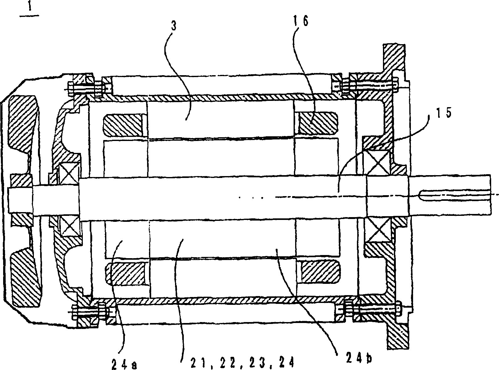
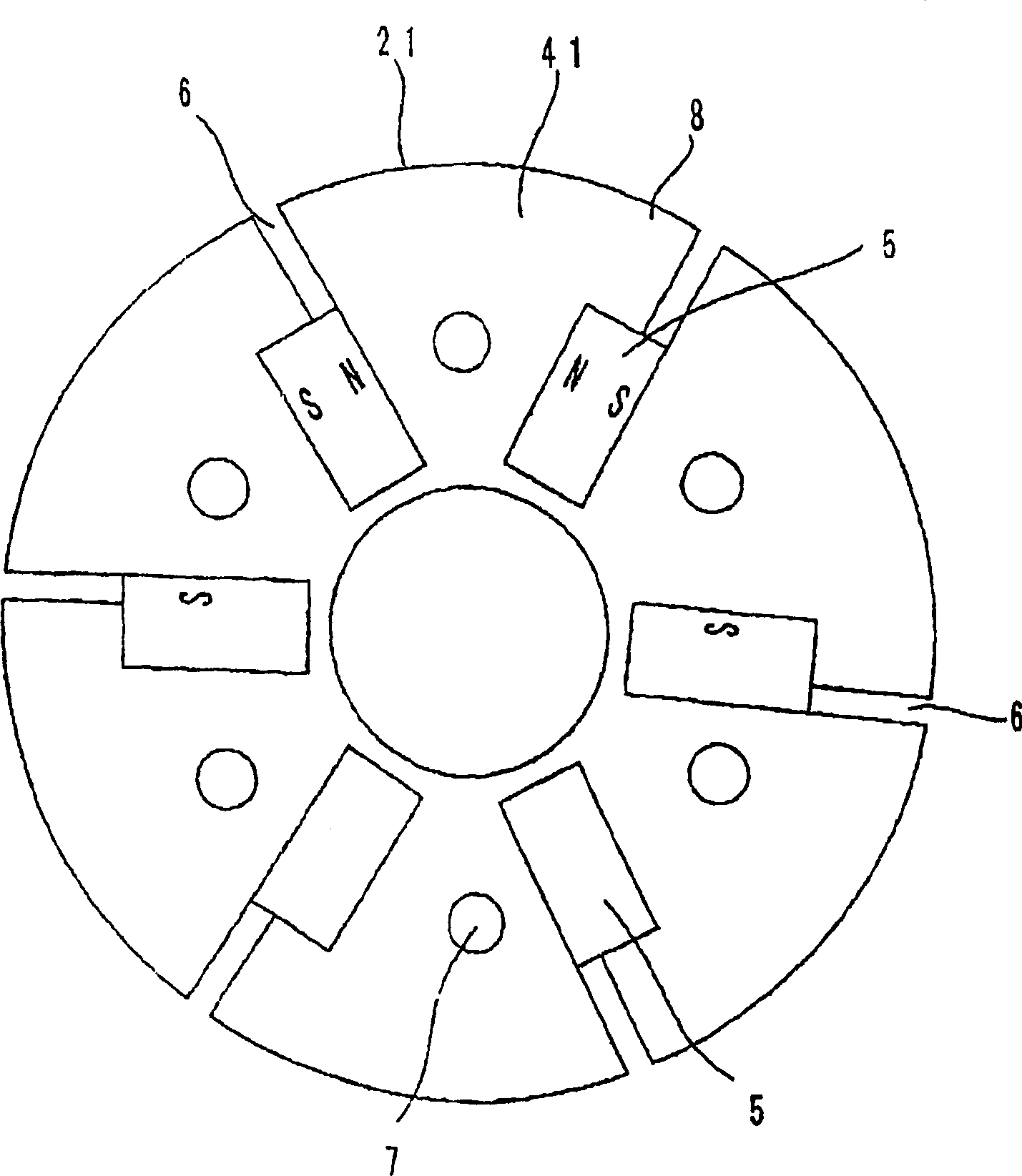
[0055] figure 1 The rotary electronic devices 1 of Embodiments 1, 2, 3 and 4 are also shown. Reference numerals 21, 22, 23, and 24 are rotors; 15, a rotating shaft; and 16, windings. figure 2 Example 1 of the present invention is shown. Reference numeral 21 is a rotor, 41 is a core magnetic pole of an electromagnetic steel sheet including the rotor 21 , and 5 is a magnet on the rotor 21 . The magnets 5 are positioned radially on the poles 41 . Reference numeral 6 is a groove, and 7 is a mounting hole.

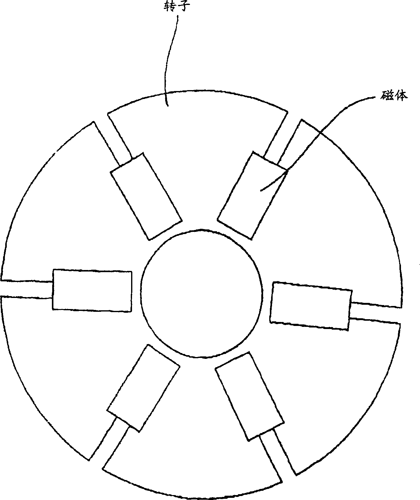
[0056] image 3 An example of a rotor structure is shown where the rotor magnets are arranged in a conventional radial manner for reference.

[0057] In the structure of the magnetic poles 41 of the rotor 21 , the magnets 5 are radially arranged, and the sub-parts 8 of the magnetic poles 41 of the rotor 21 have a convex structure formed asymmetrically. Conventionally, the subsections 8 are fo...


PUM


Abstract

A permanent magnet rotor includes permanent magnets arranged radially (5) and circularly (9) on a rotor to control the magnetic flux generated by the permanent magnets arranged radially to be approximately twice as much the magnetic flux generated by permanent magnets arranged circularly thereon.

Description

technical field [0001] The present invention relates to a magnetic pole structure capable of improving the performance and efficiency of a motor or generator using magnets for rotating machinery or transportation equipment. Background technique [0002] Synchronous motors having permanent magnets embedded therein have been widely used, and it is known that permanent magnet synchronous motors can efficiently operate at a constant speed. In particular, with the development of rare earth materials, the performance and miniaturization of permanent magnets have been significantly improved. However, the method of using permanent magnets has not been well developed, and the same is true for permanent magnet generators. [0003] For example, Japanese Patent Document No. 2001-156947 discloses a magnetic motor and generator. In this prior art, the magnets are arranged in a radial manner in the motor or generator. In addition, in order to further improve performance, the length of t...

Claims


Application Information

Patent Timeline
IPC IPC(8): H02K21/12
Inventor 木下幸雄
Owner 猪木宽至
Why Eureka
Try Eureka