Battery housing having an attached fluid flow guiding unit

A technology for battery packs and single cells, which is applied to battery pack components, primary cells to battery groups, secondary batteries, etc. Easy to stack effects

Inactive Publication Date: 2010-07-07
DAIMLER AG
View PDF0 Cites 11 Cited by
  • Summary
  • Abstract
  • Description
  • Claims
  • Application Information

AI Technical Summary

Problems solved by technology

They take up a lot of installation space and are expensive

Method used


Image

  • Battery housing having an attached fluid flow guiding unit
  • Battery housing having an attached fluid flow guiding unit
  • Battery housing having an attached fluid flow guiding unit

Examples


Embodiment Construction

[0025] Components corresponding to each other are provided with the same reference numerals in all figures.

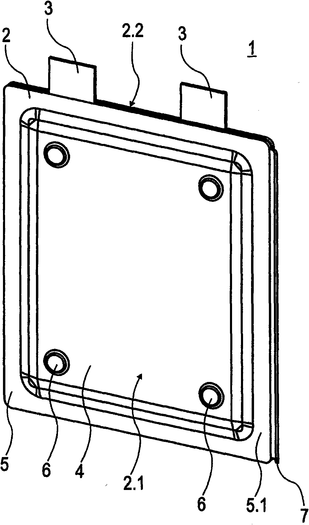
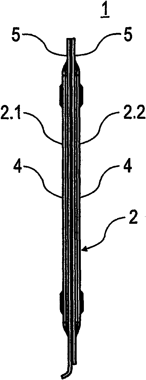
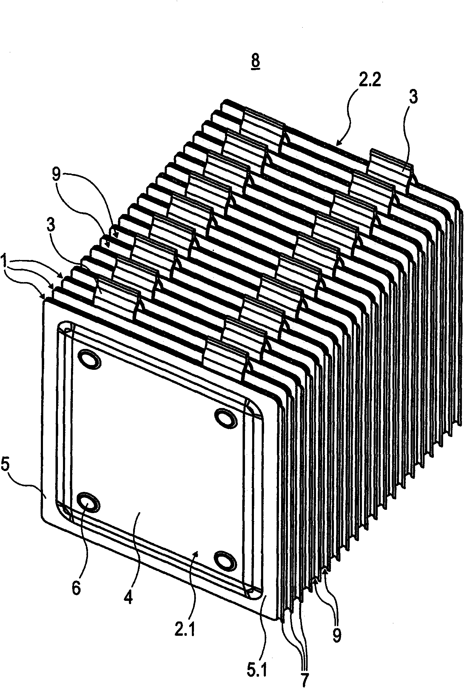
[0026] figure 1 A perspective view of the unit cell 1 is shown. The individual cells 1 are here designed as flat galvanic cells and have a cell housing 2 which is formed in particular from metal. The individual cells 1 are designed as bipolar cells each having two housing plates 2.1 and 2.2 (corresponding to mutually corresponding half-shells), which are separated by a separator. Other types of single primary cells 1 may also be provided. Here, the two housing plates 2.1, 2.2 are connected to each other at least indirectly at the edge sides, in particular connected to each other in a form-fitting and possibly material-fitting manner, in particular pressed or welded together .

[0027] The individual cells 1 have blade-shaped extensions (also called pole pieces) of the housing plates 2 . 1 and 2 . 2 as electrical connections 3 .

[0028] The individual housing plat...


PUM


Abstract

The invention relates to a battery (8), consisting of a plurality of individual cells (1), the reciprocal housing plates (2.1, 2.2) of which, preferably conducting heat well, are positioned at a distance from each other at least in sections so as to form fluid-permeable flow-through channels (9). According to the invention, a fluid flow guiding unit (7) is disposed on at least one side of the edge (5.1) of an individual cell housing (2) in an individual cell (1).

Description

technical field [0001] The invention relates to a battery pack with a plurality of individual cells, wherein, according to the preamble of claim 1 , the preferably thermally well-conducting housing walls of adjacent individual cells are at least partially spaced from one another in order to form a fluid supply. The through-flow channels, as they are used, for example, in powertrain technology, and here in particular in vehicle technology supporting at least a battery drive, are considered to be known here. Background technique [0002] In order to control the temperature of a plurality of individual cells arranged in a battery box, preferably to cool them, it is known to arrange their housings spaced apart from each other so that a fluid can flow through the gap formed by the housing walls. circulation channel. The fluid is in thermally conductive contact with the housing walls, so that the temperature of the individual cells is controlled by the fluid. [0003] High-power...

Claims


Application Information

Patent Timeline
Patent Type & Authority Applications(China)
IPC IPC(8): H01M2/10H01M10/50F28D1/03F28F13/06H01M2/02H01M6/42H01M10/04H01M50/209H01M50/224
CPCY02E60/12H01M10/0413H01M10/5004H01M10/0525H01M10/5016H01M10/5032F28F13/06H01M10/5061Y02T10/7011H01M6/42H01M2/1077H01M10/5073H01M2/0217H01M10/5095H01M10/5053H01M10/625H01M10/663H01M10/647H01M10/6554H01M10/6566H01M10/613H01M10/656Y02E60/10H01M50/103Y02P70/50H01M50/209H01M50/224
Inventor J·迈因斯歇尔D·施勒特尔
Owner DAIMLER AG
Why Eureka
Try Eureka