Laser power supply overcurrent protection circuit with locking function

A laser power supply and function technology, applied in emergency protection circuit devices, emergency protection circuit devices for limiting overcurrent/overvoltage, circuit devices, etc. Lock function, avoid inconvenience, realize the effect of overcurrent protection

Inactive Publication Date: 2012-07-04
XIAMEN UNIV
View PDF2 Cites 0 Cited by
  • Summary
  • Abstract
  • Description
  • Claims
  • Application Information

AI Technical Summary

Problems solved by technology

[0003] With the development of laser power supply technology, people have designed various laser power supply protection circuits, but most of them cut off the drive current forcibly to protect the laser after judging that the power supply has entered an overcurrent state. The disconnection action is easy to form an instantaneous kickback current in the laser power drive circuit, which is very easy to damage the laser and the equipment connected to the same power supply grid.
Some laser power supply over-current protection circuits use soft-off technology in design, that is, some delay circuits are used to avoid the instantaneous kickback current caused by sudden shutdown, but if in some occasions, such as some laser technology platform experiments In the process, the laser power supply is shut down due to over-current, which will cause the interruption of the entire experiment, and the restart of some experimental platforms will be very complicated and cumbersome, so although the laser is protected, it also causes a lot of trouble

Method used


Image

  • Laser power supply overcurrent protection circuit with locking function
  • Laser power supply overcurrent protection circuit with locking function
  • Laser power supply overcurrent protection circuit with locking function

Examples


Embodiment Construction

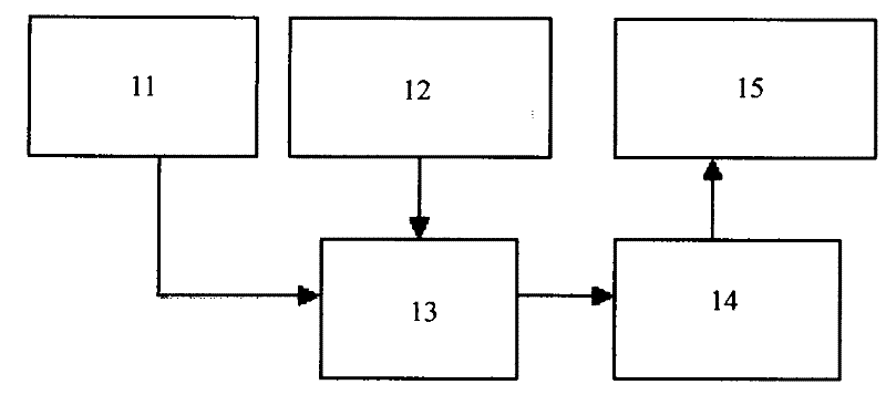
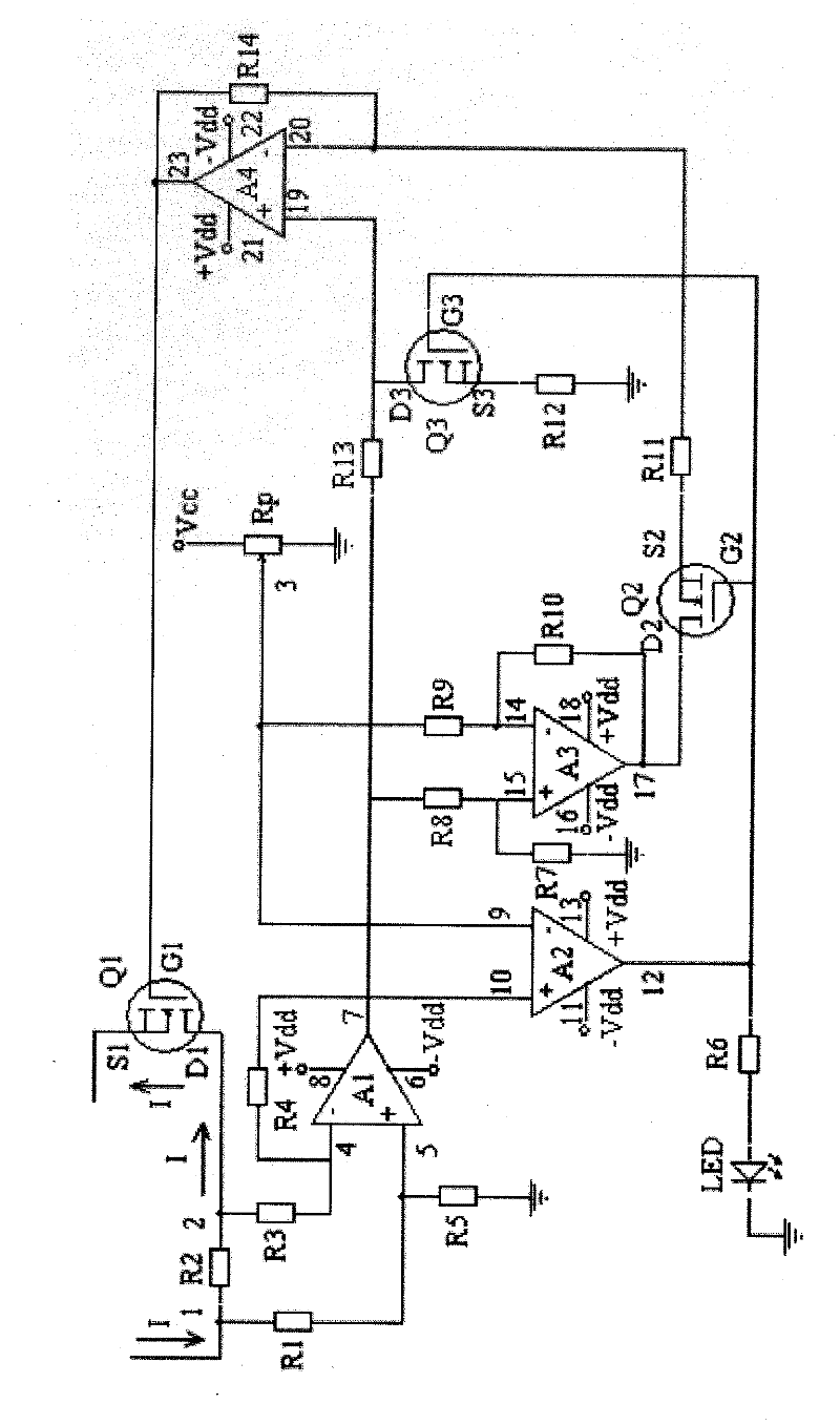
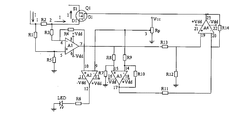
[0019] see Figure 1~3 , The present invention is provided with a current sampling conversion circuit 11, a protection current rating setter 12, a comparison control circuit 13, a function conversion circuit 14 and a loop current adjustment tube 15.

[0020] The input end of the current sampling conversion circuit 11 is externally connected to the loop drive current sampling end of the laser power supply. The current sampling conversion circuit 11 converts the loop drive current into a corresponding voltage value. The loop drive current output terminal of the current sampling conversion circuit 11 and the rated value of the protection current are set The set voltage value output terminal of the device 12 is connected to the two input terminals of the comparison control circuit 13, the comparison control circuit 13 compares the loop current value with the set protection current rating, and the comparison result of the comparison control circuit 13 controls the signal output term...


PUM


Abstract

The invention provides a laser power supply overcurrent protection circuit with a locking function, which relates to a power supply overcurrent protection circuit. The laser power supply overcurrent protection circuit is provided with a current sampling conversion circuit, a protection current rated value setting device, a comparing control circuit, a function transformation circuit and a loop current regulating tube, wherein the output end of the current sampling conversion circuit and the output end of the protection current rated value setting device are connected with the input end of thecomparing control circuit; the output end of the comparison result control signal of the comparing control circuit is connected with the input end of the function transformation circuit; the output end of the function transformation circuit is connected with the loop current regulating tube; and the loop current regulating tube is controlled to realize the safe and reliable overcurrent protectionfunction of purpose that the whole loop is in an indirectlynot switchinged off waydirectly, thereby achieving a safe and reliable overcurrent protection function. The invention can effectively realize the overcurrent protection function of the laser power supply driving current and can enable the driving current to be locked at the set rated value when the overcurrent occurs, thereby realizing the locking function of the laser power supply overcurrent protection circuit and avoiding the inconvenience caused brought by directly switching off the driving current in the commonusual overcurrent protection circuit.

Description

technical field [0001] The invention relates to a power supply overcurrent protection circuit, in particular to a laser power supply overcurrent protection circuit with a locking function. Background technique [0002] At present, lasers are widely used in all aspects of people's production and life, and the laser power supply plays a vital role as the front-end driver of the entire laser. When using the laser power supply to drive the laser, the excessive driving current can easily damage the laser itself, and at the same time cause certain damage to the equipment used together with it. Therefore, the overcurrent protection circuit in the laser power supply is necessary to ensure the normal operation of the laser. essential part. [0003] With the development of laser power supply technology, people have designed various laser power supply protection circuits, but most of them cut off the drive current forcibly to protect the laser after judging that the power supply has e...

Claims


Application Information

Patent Timeline
Patent Type & Authority Patents(China)
IPC IPC(8): H02H9/02
Inventor 蔡志平周敏张爱文许惠英王晓忠张爱清叶新荣
Owner XIAMEN UNIV
Why Eureka
Try Eureka