

Buckling device
A locking device and elastic component technology, which is applied in the field of optical communication transmission, can solve problems such as inconvenient positioning and installation, difficult installation, and elastic component falling off, so as to achieve the effect of locking and unlocking, avoiding lateral stress, and simplifying process operations
- Summary
- Abstract
- Description
- Claims
- Application Information
AI Technical Summary
Problems solved by technology
Method used
Image

Examples
Embodiment 1
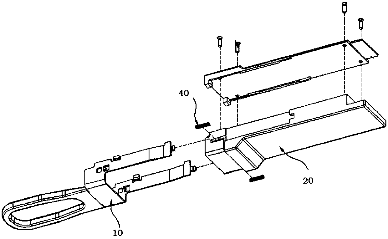
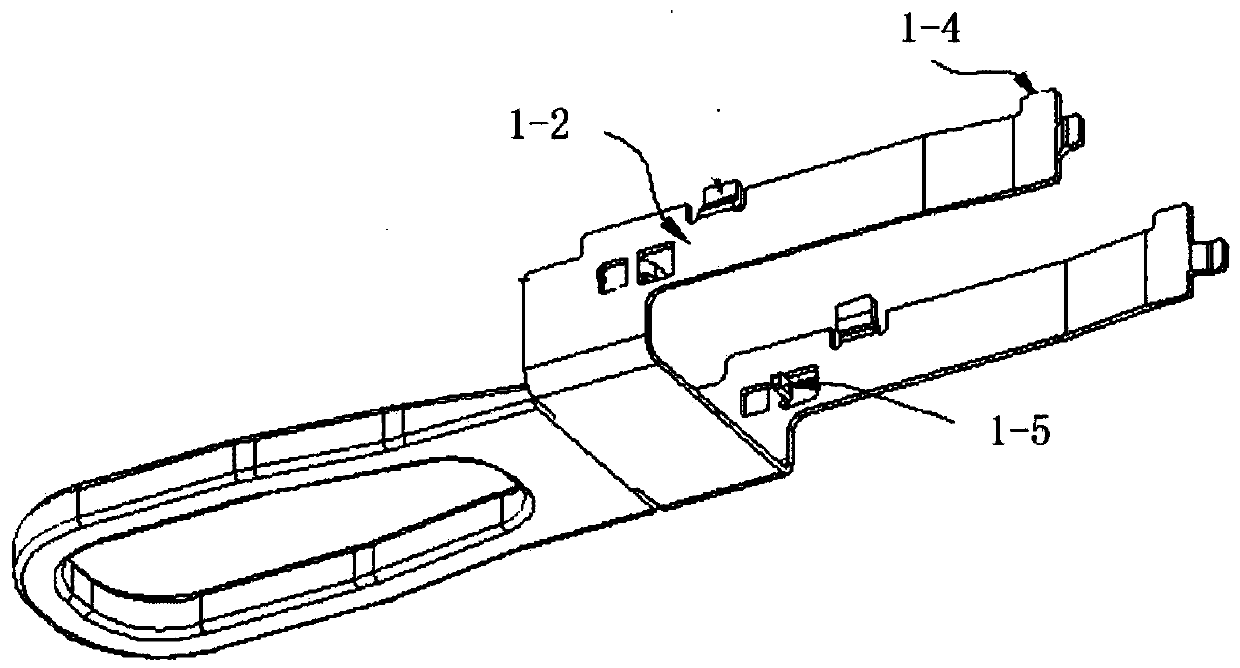
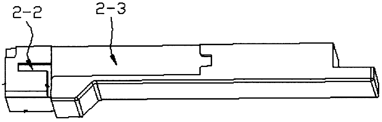
[0053] The embodiment of the present invention provides a locking device, the locking device adopts a closed cavity around to accommodate the elastic component, and the elastic component is limited in a certain space. During the installation process, the elastic component is placed in the cavity through the opening of the tunnel. Inside the body, it is easy to install and simplifies the process operation. Moreover, the elastic component is surrounded by the side wall of the cavity, which effectively avoids the generation of lateral stress, so that the elastic component can effectively move along its axis to realize the locking and unlocking functions. Furthermore, the bending part is arranged on the connecting plate of the brake pad, and the connecting plate is arranged on the housing assembly. Under the guidance of gravity, the bending part can be well accommodated in the chute, and the bending The part will not be subject to lateral stress, and under the guidance of the chan...
Embodiment 2
[0073]In order to solve the technical problem of the above-mentioned embodiment 1, the embodiment of the present invention also provides another lock decoration, which is different from the above-mentioned embodiment 1, the elastic component 3, the channel 21, the chute 22, the bending part 111 and the There are two adjusting components 4 correspondingly, and the holes 21 , sliding grooves 22 and bending parts 111 are symmetrically arranged with respect to the parts where they are arranged, so as to improve the stability of the locking device.
[0074] Combine below Figure 15 ~ Figure 19 , illustrating another implementation manner of the locking device in the embodiment of the present invention.
[0075] refer to Figure 15 , in this embodiment, the locking device includes a brake pad 1, a housing assembly 2, and an elastic assembly 3. The sheet 1 can lock the housing assembly 2 in the shielding cage to achieve optical interconnection; when the housing assembly 2 needs to ...
PUM
 Abstract
Description
Claims
Application Information