Wing folding and locking assembly and unmanned aerial vehicle

A locking component and wing folding technology, applied in the field of drones, can solve the problems of incomplete folding and unfolding locking functions of folding locking devices, incomplete folding and unfolding locking functions of UAV wings, etc.

Pending Publication Date: 2018-03-09
成都云鼎智控科技有限公司
View PDF0 Cites 4 Cited by
  • Summary
  • Abstract
  • Description
  • Claims
  • Application Information

AI Technical Summary

Problems solved by technology

[0004] The first purpose of the present invention is: in order to solve the problem of incomplete folding and unfolding locking of the folding locking device, the present invention provides a wing folding locking assembly
[0005] The second purpose of the present invention is to solve the problem of incomplete folding and unfolding of the wing of the drone, the present invention provides a drone

Method used


Image

  • Wing folding and locking assembly and unmanned aerial vehicle
  • Wing folding and locking assembly and unmanned aerial vehicle
  • Wing folding and locking assembly and unmanned aerial vehicle

Examples


Embodiment 1

[0032] Example 1, see Figure 1-Figure 6

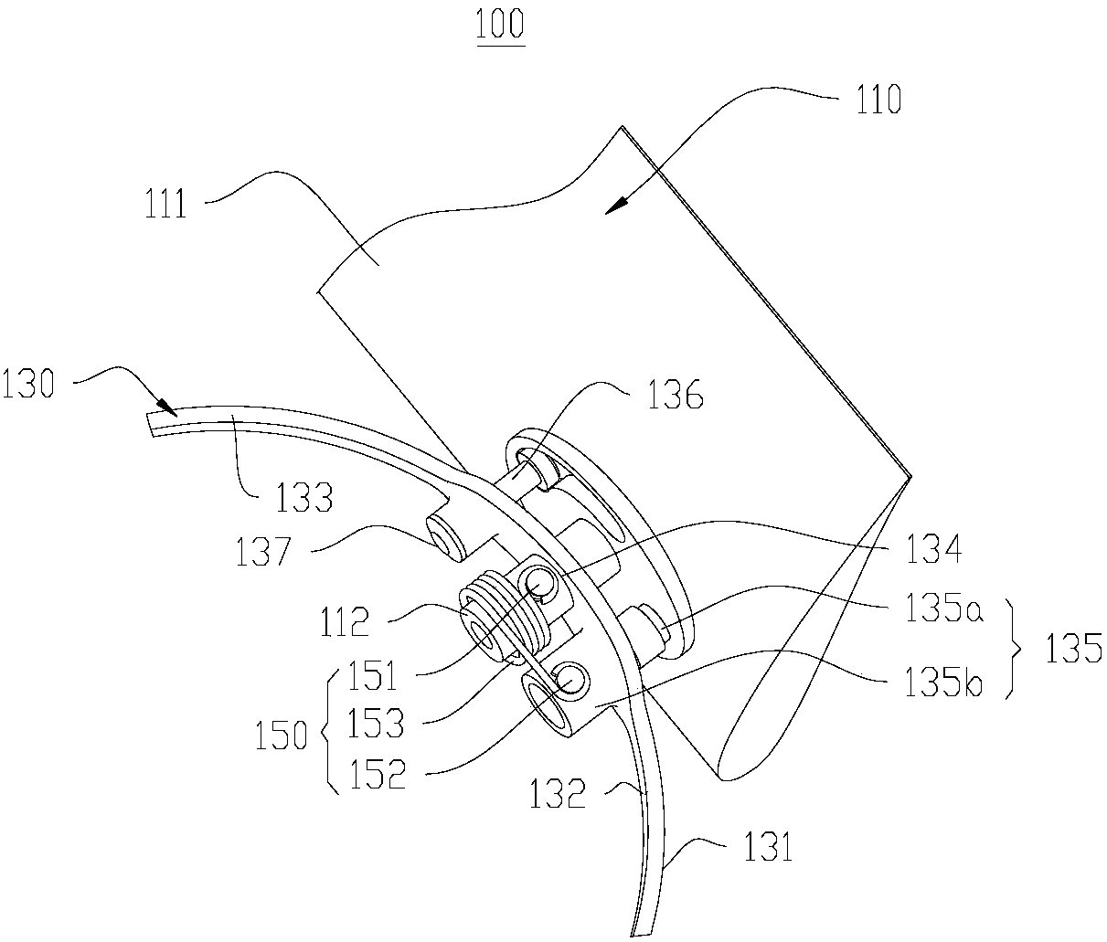
[0033] Such as figure 1 As shown, the present embodiment provides a wing folding locking assembly 100 . The wing folding locking assembly 100 includes a wing 110 , a fixing seat 130 and a folding mechanism 150 . The folding mechanism 150 is connected with the fixing base 130 and the wing 110 at the same time, so as to control the folding or unfolding of the wing 110 relative to the fixing base 130 .

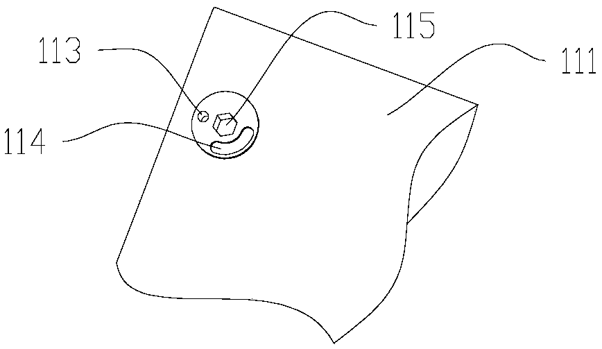
[0034] Specifically, the fixing seat 130 includes a main body 133 , and the main body 133 includes an installation portion 134 and a connecting piece 135 arranged at intervals. The wing 110 includes a wing body 111 and a wing shaft 112 . Both ends of the wing body 111 are respectively connected to the wing body 111 and the mounting portion 134 .

[0035] combine figure 1 and figure 2 As shown, the connecting member 135 is provided with an elastic limiting portion 135a at an end close to the wing body 111 , and the wing body 111 i...

Embodiment 2

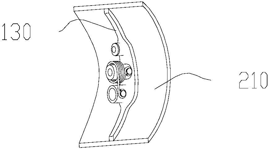
[0047] The wing folding locking assembly 100 and the UAV 200 provided in Embodiment 1 have basically realized that the wing 110 can be in a folded state in the launch tube, and after the UAV 200 is launched out of the tube, the wing 110 can be automatically unlocked and unfolded , and the function of locking at the prescribed position is different from Embodiment 1 (see Embodiment 1 for the unmentioned part):

[0048] In this embodiment, the fixing seat 130 is provided with a sleeve (not shown in the figure), and the sleeve is embedded in the installation part 134, and the wing shaft 112 is sleeved inside the sleeve, and the wing shaft 112 is detachably connected to the inside of the sleeve. . At this time, the first pin 151 is disposed on the portion of the sleeve protruding from the second side 132 , and the torsion spring 153 is sleeved on the sleeve. The advantage of such setting is that it can protect the wing shaft 112 and improve the service life of the wing folding lo...


PUM


Abstract

The invention discloses a wing folding locking assembly and an unmanned aerial vehicle, and relates to the technical field of unmanned aerial vehicles. A wing folding locking assembly includes a wing, a fixing seat and a folding mechanism. The folding mechanism is connected with the fixed seat and the wing at the same time, so as to control the folded or unfolded state of the wing relative to the fixed seat. The fixing seat includes a main body, and the main body includes installation parts and connecting pieces arranged at intervals. The wing comprises a wing body and a wing shaft. The two ends of the wing body are respectively connected with the wing body and the installation part. The end of the connecting piece close to the wing body is provided with an elastic limiting part, and the wing body is provided with a positioning hole, and the limiting part cooperates with the positioning hole. An unmanned aerial vehicle, comprising the above-mentioned wing folding locking assembly. The wing folding and locking component can realize the folding, unfolding and locking functions of the drone's wings without using other power sources.

Description

technical field [0001] The invention relates to the technical field of unmanned aerial vehicles, and more specifically relates to a wing folding locking assembly and an unmanned aerial vehicle. Background technique [0002] In the barrel-launched UAV, due to the very narrow lateral space, when the UAV is in the barrel, the wings need to be folded. Lock the position to provide lift for the UAV, thus ensuring the normal flight of the UAV. [0003] At present, the common wing folding methods mainly include roll-folding, submerged, tail-folding, longitudinal folding, and horizontal folding. The unfolding locking structure is mostly a spring mechanism, and a gas pressure system formed by a hydraulic system or pyrotechnics is also used. In environments with high levels of vibration or other severe conditions, the current folding and locking devices have defects such as incomplete folding and unfolding locking functions, easy loosening and poor results. Contents of the inventio...

Claims


Application Information

Patent Timeline
Patent Type & Authority Applications(China)
IPC IPC(8): B64C3/56
CPCB64C3/56
Inventor 唐冰陈绪安刘以建
Owner 成都云鼎智控科技有限公司
Why Eureka
Try Eureka