Unmanned aerial vehicle landing interface

a technology for unmanned aerial vehicles and landing interfaces, which is applied in the direction of aircraft, arresting gear, transportation and packaging, etc., can solve the problems of not allowing the operator to maintain and affecting the operation of the unmanned aerial vehicle. , to achieve the effect of convenient interfa

Inactive Publication Date: 2016-01-07
SKYCATCH
View PDF13 Cites 197 Cited by
  • Summary
  • Abstract
  • Description
  • Claims
  • Application Information

AI Technical Summary

Benefits of technology

[0010]The principles described herein provide benefits and / or solve one or more of the foregoing or other problems in the art with systems and methods that enable autonomous landing of an unmanned aerial vehicle (UAV). In particular, one or more embodiments described herein include systems and methods that enable a UAV to conveniently interface with and land within a UAV ground station (UAVGS). For example, one or more embodiments include a UAV that includes a landing base and landing frame that interfaces with a landing housing of a UAVGS in a manner that allows the UAV to automatically land with accuracy.
[0011]For example, in one or more embodiments, systems and methods include features that cause the UAV to guide itself within a landing housing of the UAVGS. For instance, the UAV can include a landing base having a complementary shape to a shape of the landing housing of the UAVGS. When the UAV comes into contact with the UAVGS, the shape of the landing base and / or the landing housing can cause the UAV to self-align within the UAVGS as the UAV docks within the landing housing of the UAVGS. As such, the UAV can safely land within the UAVGS with minimal error and without a substantial risk of damaging or destroying the UAV during a UAV landing.

Problems solved by technology

This becomes problematic, however, when the UAV is deployed over harsh terrain (e.g., mountains) or over large areas of land.
In such cases, an operator would have difficulty finding a control position (e.g., the physical location of the operator) to allow the operator to successfully control the UAV.
For instance, mountains or large areas of land will generally not allow an operator to maintain the UAV within a viewing range to successfully operate the UAV.
In a long-range remote control scenario, however, additional problems arise with conventional UAVs and conventional UAV systems.
The remote landing process for an operator, however, is often difficult and error-prone, which increases the probability of damaging or destroying a UAV, resulting in considerable expense.
In addition, a damaged UAV can delay a project, causing additional time and expense.
Frequently, however, an operator requires extensive training and practice to be able to successfully remotely land a UAV on a consistent basis.
The time and expense required to train an operator to perform remote UAV landings is cost prohibitive to many companies that would benefit from the use of a UAV.
Moreover, even when adequately trained, an operator still has a fairly high risk of damaging or destroying a UAV during a remote UAV landing.

Method used


Image

  • Unmanned aerial vehicle landing interface
  • Unmanned aerial vehicle landing interface
  • Unmanned aerial vehicle landing interface

Examples


Embodiment Construction

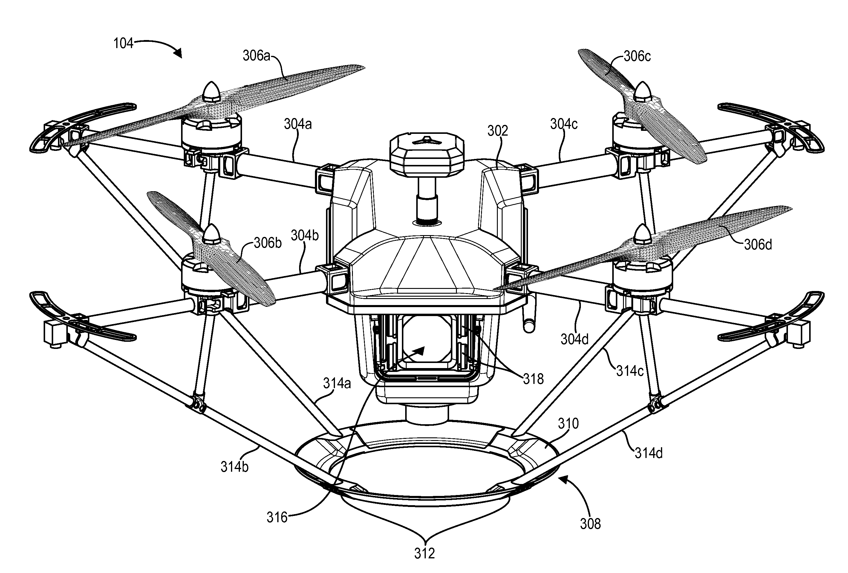
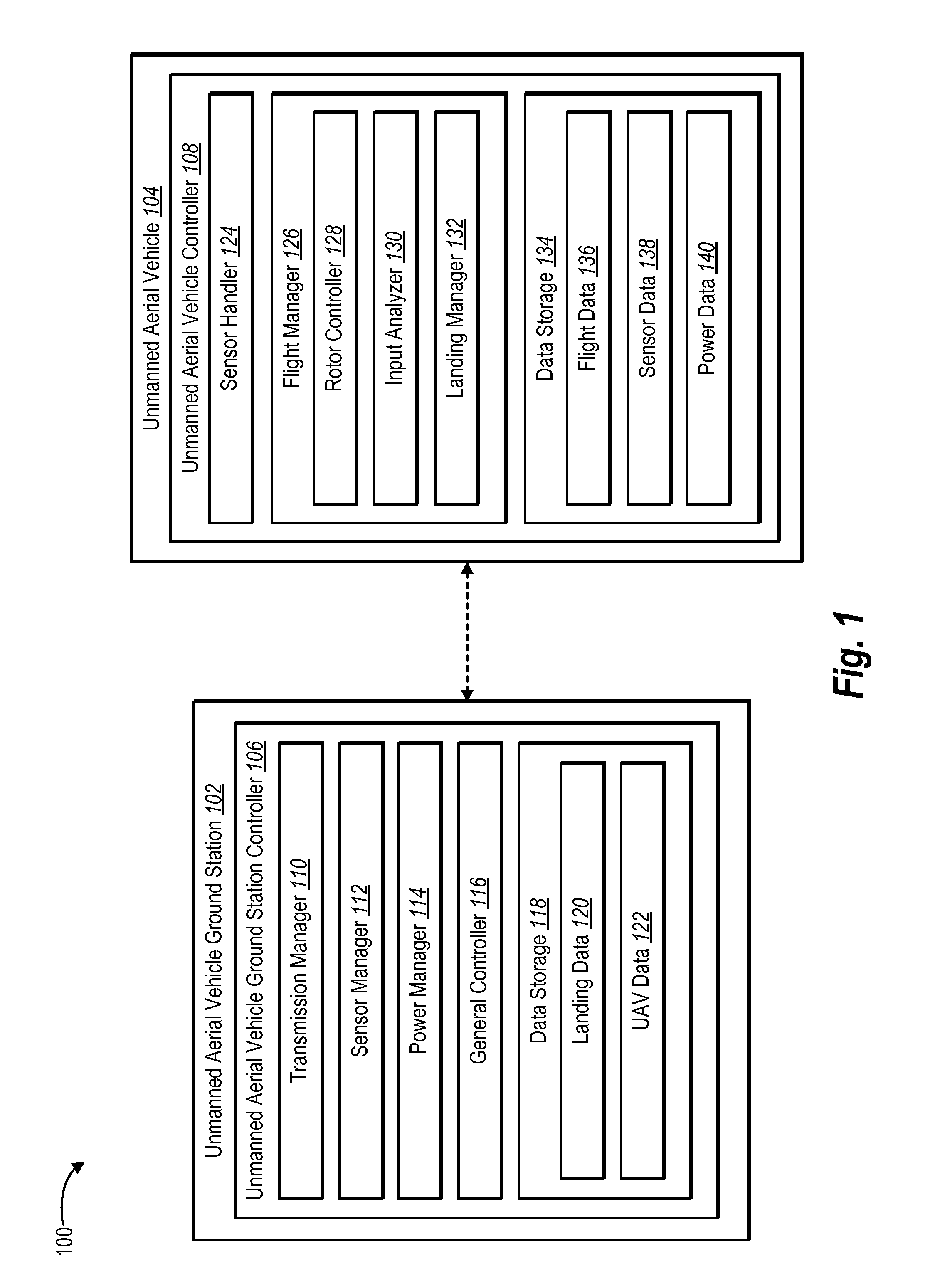
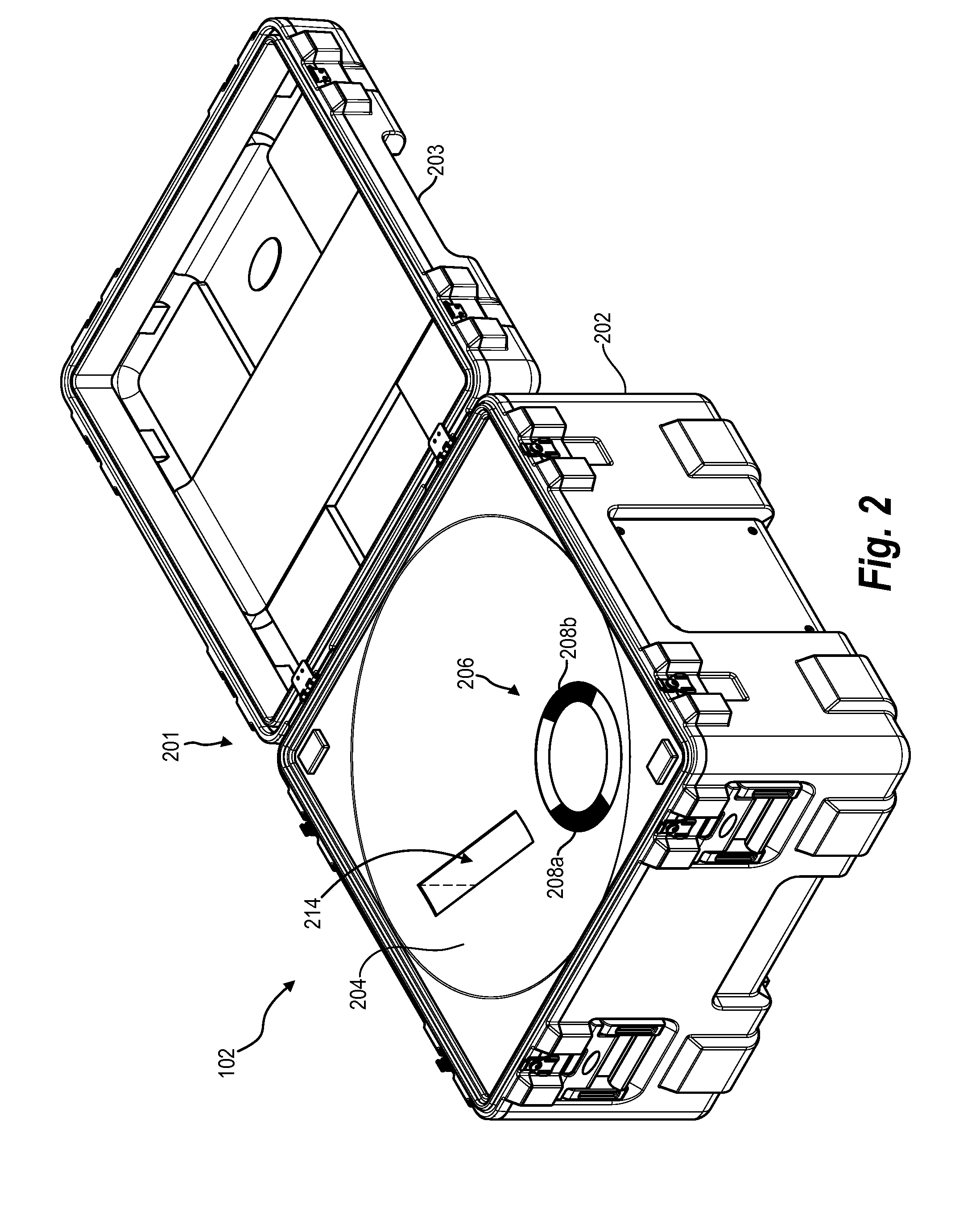
[0025]One or more embodiments described herein include an autonomous landing system. For example, the autonomous landing system described herein manages an autonomous landing of a UAV in connection with a UAVGS. The autonomous landing system described herein includes components that enable a UAV to autonomously land within a landing housing of a UAVGS. For example, in one or more embodiments, an autonomous landing system includes a UAV having a main body, one or more rotors coupled to the main body, and a landing base coupled to the main body. Additionally, the autonomous landing system can include a UAVGS that includes a landing housing that receives the UAV when the UAV lands within the UAVGS. In one or more embodiments, the landing base has a size and shape that enables the UAV to land within a complimentary-shaped landing housing of the UAVGS and interface with one or more components of the UAVGS.

[0026]In one or more embodiments, the autonomous landing system includes a self-ali...


PUM


Abstract

The present disclosure is directed toward systems and methods for autonomously landing an unmanned aerial vehicle (UAV). In particular, systems and methods described herein enable a UAV to land within and interface with a UAV ground station (UAVGS). In particular, one or more embodiments described herein include systems and methods that enable a UAV to conveniently interface with and land within a UAV ground station (UAVGS). For example, one or more embodiments include a UAV that includes a landing base and landing frame that interfaces with a landing housing of a UAVGS.

Description

CROSS-REFERENCE TO RELATED APPLICATIONS[0001]This application is a continuation-in-part of U.S. patent application Ser. No. 14 / 586,913, filed Dec. 30, 2014, which claims the benefit of and priority to U.S. Provisional Patent Application 62 / 020,126, filed Jul. 2, 2014. The entire contents of the foregoing patent application are hereby incorporated by reference.BACKGROUND[0002]1. Technical Field[0003]One or more embodiments of the present disclosure generally relate to autonomous flight of an unmanned aerial vehicle (UAV). More specifically, one or more embodiments relate to landing a UAV and interfacing the UAV within a UAV ground station (UAVGS).[0004]2. Background and Relevant Art[0005]Aerial photography and videography are becoming increasingly common in providing images and videos in various industries. For example, aerial photography and videography provides tools for construction, farming, real estate, search and rescue, and surveillance. In recent years, UAVs have provided an ...

Claims


Application Information

Patent Timeline
Patent Type & Authority Applications(United States)
IPC IPC(8): B64C39/02B64C27/08H02J7/00
CPCB64C39/024B64C27/08H02J7/0042B64C2201/146B64C2201/042B64C2201/108B64C2201/024B64F1/02H02J7/0044B64U10/13B64U30/20B64U2201/20B64U70/30B64U80/70B64C25/00B64U70/00
Inventor SANZ, CHRISTIANMILLER, SAMUEL GILESNOORANI, JONATHAN SHYAUNSIRANG, BEHROOZE
Owner SKYCATCH
Why Eureka
Try Eureka