
DLP display screen system and splicing method thereof

A technology for display systems and display screens, which is applied to parts of TV systems, TVs, and color TVs. Low heat generation and low power consumption

Inactive Publication Date: 2010-07-14
SCT OPTRONICS +1
View PDF0 Cites 9 Cited by
  • Summary
  • Abstract
  • Description
  • Claims
  • Application Information

AI Technical Summary

Problems solved by technology

[0009] In order to solve the shortcomings of the plasma splicing screen in the prior art due to its own display technology: high energy consumption, high heat generation and cannot be used for long-term work and long-time display of still pictures and high-resolution display This technical problem is different from traditional When the DLP rear projection splicing unit displays images with a ratio of 4:3, there will be very wide black areas on the upper and lower parts of the display screen, which looks very ugly and cannot fully utilize the display area of ​​the entire screen. The present invention provides a A 16:9 DLP Display System

Method used


Image

  • DLP display screen system and splicing method thereof
  • DLP display screen system and splicing method thereof
  • DLP display screen system and splicing method thereof

Examples


Embodiment Construction

[0029] The utility model is described below in conjunction with accompanying drawing:

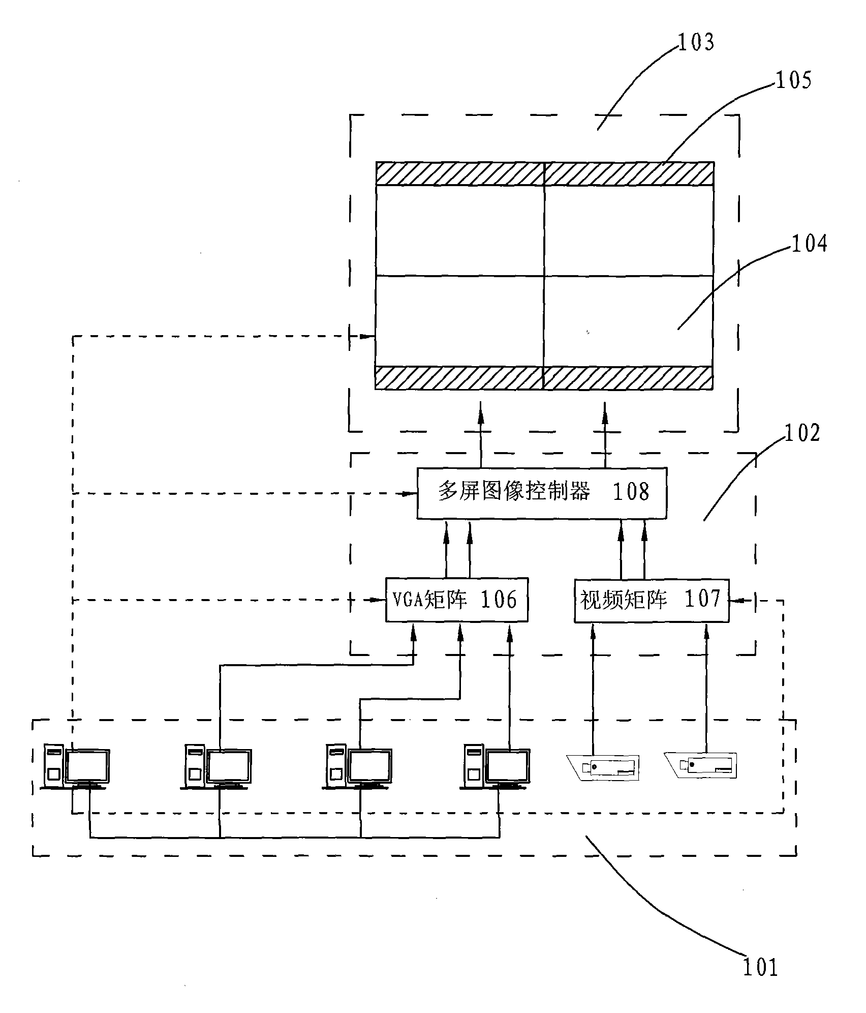
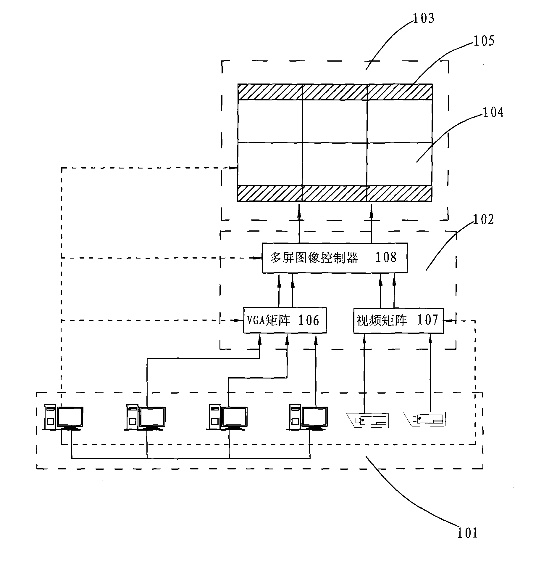
[0030] see figure 1 and figure 2 . As shown in the figure, the DLP display system includes: a signal input terminal 101, an information transmission unit 102 and a 16:9 DLP widescreen display terminal 103, wherein the signal input terminal 101 is connected to the information transmission unit 102, and the The information transmission unit 102 is connected to the 16:9 DLP widescreen display terminal 103 .

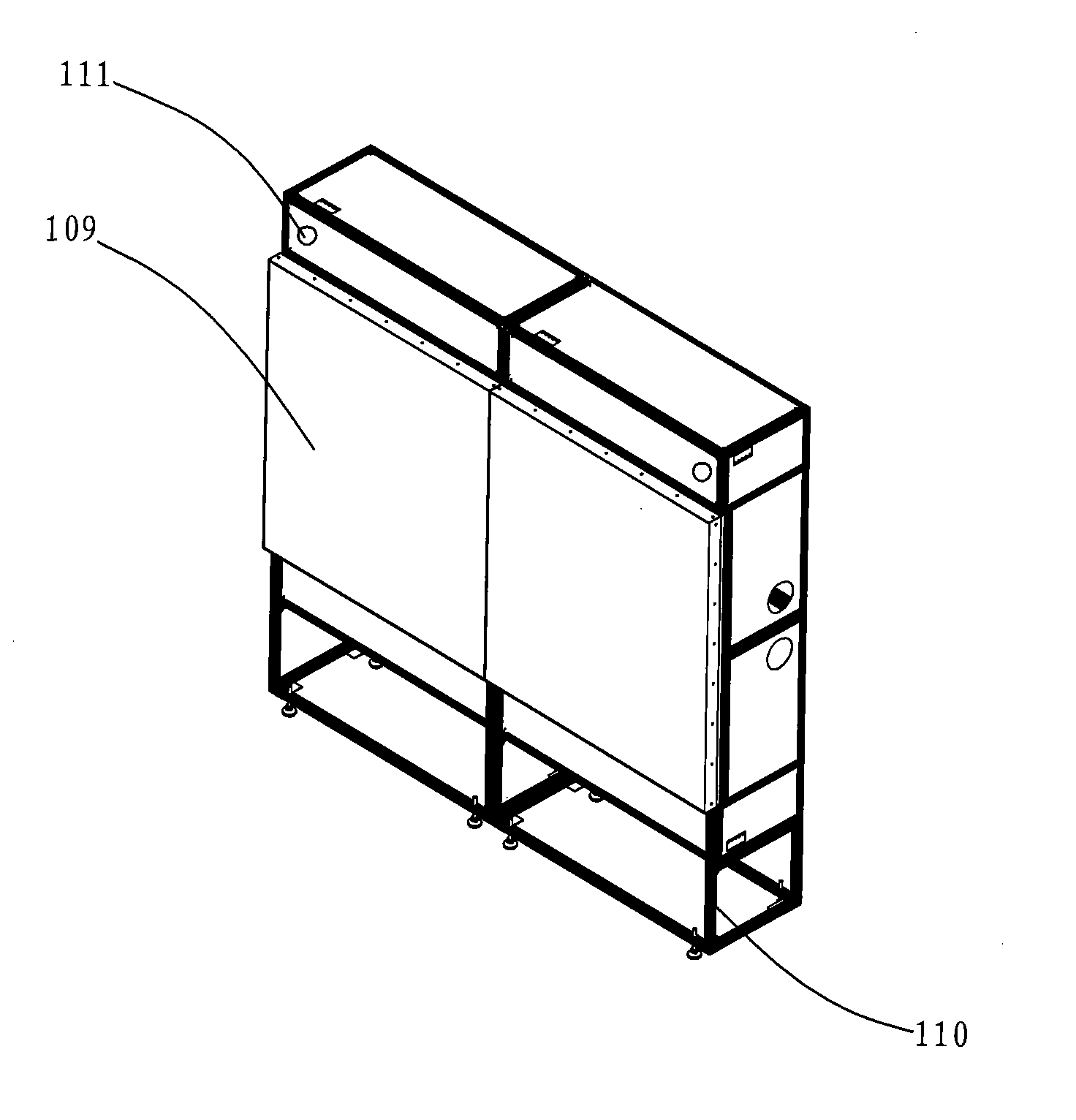
[0031] In the preferred technical solution of the present invention: the 16:9 DLP widescreen display terminal 103 includes a 16:9 DLP display 104 , and the 16:9 DLP display 104 is driven by a 16:9 optical engine 105 . The 16:9 optical engine 105 is installed above and / or below the 16:9 DLP display screen 104, and the installation position can be referred to in conjunction with image 3 A schematic diagram of the overall structure of a 16:9 DLP splicing screen in a DLP display screen ...


PUM


Abstract

The invention relates to a DLP display screen system and a splicing method thereof. The DLP display screen system comprises: a signal input end, an information transmission unit and a 16:9 DLP wide-screen display terminal, wherein the signal input end is connected with the information transmission unit which is connected with the 16:9 DLP wide-screen display terminal. The DLP display screen splicing method comprises the steps: installing 16:9 DLP single-screens in a frame one by one based on a 2 x N mode and installing 16:9 light-emitting machines above and / or below the 16:9 DLP display screen. The 16:9 DLP display screen system has good display effect, low use cost, low power consumption and small amount of heat dissipation, and is suitable for most long-time indoor display. By adopting the DLP display screen splicing method according to the invention, small splicing seam between screens is achieved, and the 16:9 light-emitting machines are arranged at the upper and lower ends of thespliced screen, so no space for maintenance is required in advance, which reduces the thickness of the screen.

Description

technical field [0001] The invention relates to a large-screen display and installation technology, in particular to a 16:9 DLP display system and a splicing method. Background technique [0002] In conventional large-screen display systems, splicing display units with a display ratio of 4:3 are usually used; while the current 16:9 widescreen display units used for splicing screens are only plasma splicing screens or LCD splicing screens. The splicing seam of the screen is as wide as 12mm, which cannot be compared with the DLP splicing screen and will not be mentioned for the time being. For the plasma splicing screen, due to the shortcomings of its own display technology: high energy consumption, high heat generation and large seams (6mm wide), it cannot be used for long-term work and long-time display of still images and high-resolution displays. [0003] The following describes the defects of the widely used plasma splicing screen in the prior art: [0004] Display tech...

Claims


Application Information

Patent Timeline
IPC IPC(8): H04N5/74H04N9/31
Inventor 张丽婵谭绍红
Owner SCT OPTRONICS
Learn More