
Method for the optimised movement co-ordination of measuring tools or machine-tools by means of redundant translatory axles

A technology of translational movement and measuring machine, which is applied in the direction of computer control, general control system, control/regulation system, etc., and can solve the problems of inability to cope with pre-planning, undisclosed solutions, and inability to automate module combinations in applications.

Active Publication Date: 2010-07-21
TRUMPF WERKZEUGMASCHINEN GMBH & CO KG
View PDF8 Cites 4 Cited by
  • Summary
  • Abstract
  • Description
  • Claims
  • Application Information

AI Technical Summary

Problems solved by technology

The superimposed rapid movement can then be synchronized with the constant main movement without any problems - a perfectly common approach, but one which in its application is hardly able to cope without special pre-planning
[0022] However, what is required in the case of the present problem is to go through sections almost without interruption with different labels, different time requirements and different sizes, where in turn the transfer movement must be adapted to this until the momentary movement reversal - and all this is usually in two dimensions - that is: even experienced specialists cannot programmatically combine them from the currently available automation modules of modern control devices
Corresponding, multifacetedly usable solutions have not been disclosed so far
[0023] In addition to the limitation of optimal motion coordination for a large number of closely adjacent small part contours, there is an additional problem for many measuring or processing machines with redundant, translationally acting axes: If the underlying problem is to be solved, The prior art to date assumes that after each high-acceleration movement, the correspondingly advanced additional axis is eventually overtaken by the base axis again, so that it is again in its starting position, usually in the center of its current range of motion
Since most of the additional axes for synchronous, redundantly acting operation according to the old state of the art require only a relatively short range of motion, this is in the best case a rather minor problem

Method used


Image

  • Method for the optimised movement co-ordination of measuring tools or machine-tools by means of redundant translatory axles
  • Method for the optimised movement co-ordination of measuring tools or machine-tools by means of redundant translatory axles
  • Method for the optimised movement co-ordination of measuring tools or machine-tools by means of redundant translatory axles

Examples


Embodiment Construction

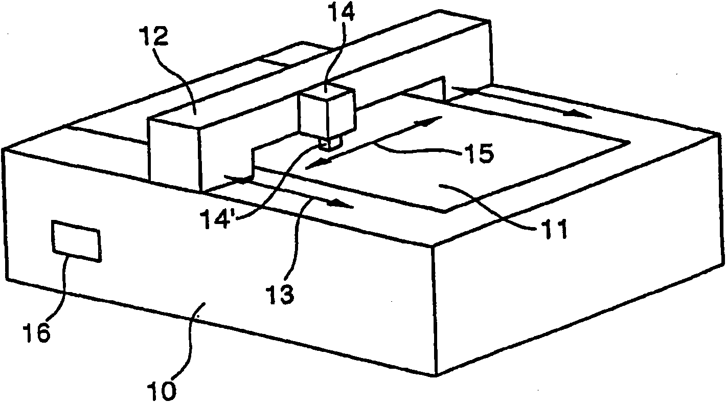
[0060] figure 1 A machine tool 10 is shown in which a workpiece 11 is arranged in a stationary manner. The frame 12 is movable in the axial direction 13 . On this frame 12, be provided with device 14, be provided with tool holder 14 ' again on this device 14, this tool holder 14 ' can hold cutting tool. The device 14 (and thus the toolholder 14' together with the tool) is movable in an axial direction 15. The toolholder 14' is also movable relative to the device 14 in the axial direction 13. Depend on figure 1 It can be seen that the toolholder 14' (with the tool) has a lower mass than the device 14, which can be called a slide. The frame 12 with the associated drive is the first partial shaft acting in the direction 13 and is referred to as the base shaft, while the tool holder 14' with the associated drive is the second partial shaft acting in the axial direction 13, i.e. additional axis. The base axis has a larger range of motion and lower acceleration than the...


PUM


Abstract

The invention relates to a method for the optimised movement co-ordination of measuring tools or machine-tools by means of redundant translatory axles, each longer partial axle enabling a relatively low-acceleration partial movement over a relatively large measuring or machining space, and each shorter partial axle carrying out, at an essentially generally constant measuring or machining speed, essentially the movement components of an entire movement, which require acceleration above the maximum determined for each longer partial axle. The invention is characterised in that, when positions are reached, which would otherwise not be reached in a non-divided movement, the base axles can brake correspondingly and even come to a complete standstill. The movement component of the base axles which is missing for the entire movement is compensated by the simultaneous displacement of the neutral starting point of the additional axles.

Description

technical field [0001] In the development of measuring machines and machine tools, redundant, translationally acting axes are increasingly being used, i.e. axes which are superimposed on one another, constructively or interacting, and can move parallel in space relative to each other, wherein One or more additional axes with a relatively short range of motion are arranged on or relative to a base shaft with a relatively long range of motion. Background technique [0002] Such axes, which can be moved redundantly in the same direction superimposedly, offer the possibility of combining a large range of movement of the base axis with a short range during the continuous movement of the measuring device or tool relative to the measured or processed object. The higher acceleration capacity of the additional shaft, which is thus lightly constructed, [0003] An example of such a design is patent EP 594 699 B1 (Ehlerding). In said patent it has already been proposed to use paralle...

Claims


Application Information

Patent Timeline
IPC IPC(8): G05B19/402G05B19/404
CPCG05B19/402G05B2219/41457G05B2219/49284G05B2219/50019G05B2219/42209G05B19/404B23Q1/445
Inventor A·埃勒丁
Owner TRUMPF WERKZEUGMASCHINEN GMBH & CO KG
Learn More