Mobile communication base station antenna

A technology for mobile communication and base station antennas, which is applied to antennas, antenna arrays that are energized separately, and antenna components, etc. It can solve problems such as the verification of space diversity effects, achieve high speed, and increase data communication capacity.

Inactive Publication Date: 2010-07-28
HITACHI CABLE
View PDF3 Cites 6 Cited by
  • Summary
  • Abstract
  • Description
  • Claims
  • Application Information

AI Technical Summary

Problems solved by technology

[0016] However, in Non-Patent Document 2, the effectiveness of vertically arranged space diversity antennas is clarified theoretically and experimentally only from the perspective of antenna spacing and correlation coefficients, and the verification of the space diversity effect remains
That is, in Non-Patent Document 2, there is no mention of the array antenna structure for realizing space division multiple access

Method used


Image

  • Mobile communication base station antenna
  • Mobile communication base station antenna
  • Mobile communication base station antenna

Examples


Embodiment 1

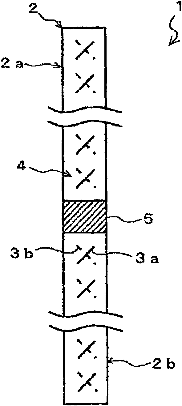
[0046] figure 1 It is a schematic diagram showing the base station antenna for mobile communication according to this embodiment.

[0047] Such as figure 1As shown, the base station antenna 1 for mobile communication has more than two array antennas ( figure 1 There are two in the middle), and each array antenna 2 is arranged at a predetermined interval in the vertical direction. In this embodiment, a case where two array antennas 2a, 2b are arranged in the vertical direction will be described.

[0048] The array antennas 2 a and 2 b are connected by a conductive plate 5 . The conductive plate 5 provides a common ground potential (GND potential) to the two array antennas 2a, 2b.

[0049] The array antennas 2a and 2b are arranged at a predetermined distance apart in the vertical direction.

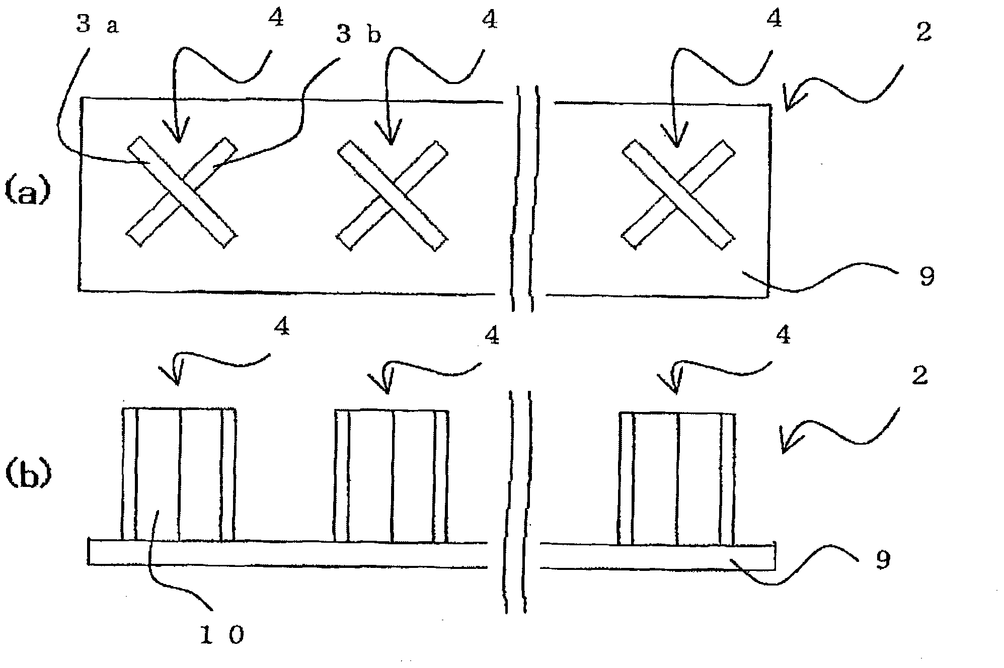
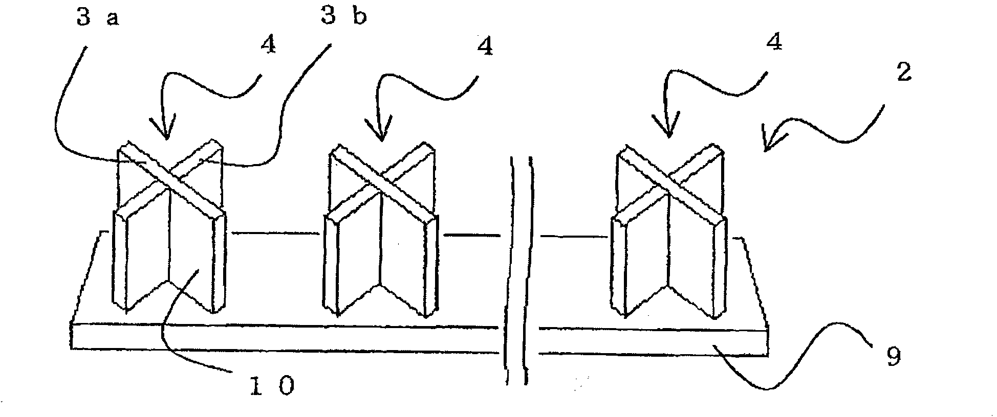
[0050] The array antennas 2a and 2b are antennas in which a plurality of antenna element pairs 4 are arranged in an array. The antenna element pair 4 is composed of two antenna elemen...

Embodiment 2

[0080] Next, other embodiments of the present invention will be described.

[0081] Figure 8The base station antenna 61 shown for mobile communication is instead of the figure 1 In the base station antenna 1 for mobile communication, the array antenna 2 in which the pairs of ±45-degree antenna elements 4 are arranged in an array is used, and the array antenna 63 in which the horizontal and vertical antenna elements 62 are arranged in an array is used. The horizontal-vertical antenna element pair 62 is an antenna element pair in which one antenna element 64 a is arranged vertically and the other antenna element 64 b is arranged horizontally.

[0082] The base station antenna 61 for mobile communication is due to the figure 1 In the mobile communication base station antenna 1, the ±45-degree antenna element pair 4 is changed to a horizontal and vertical antenna element pair 62, so it can be obtained with figure 1 The base station antenna 1 for mobile communication has the sa...

Embodiment 3

[0084] Next, the base station antenna 71 for mobile communication of the third embodiment will be described below.

[0085] Figure 9 It is a schematic diagram showing the mobile communication base station antenna 71 according to the third embodiment of the present invention.

[0086] Figure 9 The illustrated base station antenna 71 for mobile communication is an antenna in which an array antenna 2 in which pairs of ±45-degree antenna elements 4 are arranged in an array and an array antenna 63 in which pairs of horizontal and vertical antenna elements 62 are arranged in an array are arranged in the vertical direction. .

[0087] The polarization directions of the array antenna 2 and the array antenna 63 are different, so when the array antenna 2 and the array antenna 63 are arranged adjacently, compared with the occasion where the array antennas 2 and the array antennas 63 are arranged adjacently, the size of the array antenna 2 can be reduced. , Antenna correlation coeffi...


PUM


Abstract

The invention provides a mobile communication base station antenna capable of realizing the spatial subdivision multiple access with no need for greatlu increasing the arrangement area of the present mobile communication base station antenna. The mobile communication base station antenna is formed by two orthogonally arranged antenna elements (3) and has two or more array antennas (2) for arranging a plurality of antenna element pairs (14) in array shape to improve the use efficiency of the frequent and enlarge the channel capacity. The array antennas (2) are arranged with a predetermined distance in a vertical direction.

Description

technical field [0001] The invention relates to a polarized wave shared antenna and an array antenna, in particular to a mobile communication base station antenna for realizing space division multiple access. Background technique [0002] In the base station used in mobile communication, in order to realize simultaneous connection of multiple users, methods such as Frequency Division Multiple Access (FDMA), Time Division Multiple Access (TDMA), and Symbol Division Multiple Access (CDMA) have been proposed. Import commercial systems. [0003] However, with the popularization of mobile communication in recent years, the number of users has increased rapidly, and calls have been requested that exceed the allowable amount of frequency channels allocated to the mobile communication system, causing problems such as frequency shortage. [0004] Therefore, in order to improve frequency utilization efficiency and realize expansion of channel capacity, a space division multiple acces...

Claims


Application Information

Patent Timeline
Patent Type & Authority Applications(China)
IPC IPC(8): H01Q21/08
CPCH01Q21/08H01Q1/246H01Q21/26
Inventor 清水隆行村野慎介安藤敏之
Owner HITACHI CABLE
Why Eureka
Try Eureka