Ultrasonic humidifier and atomizing device thereof

A technology of atomization device and humidifier, which is applied to ultrasonic humidifier, spray device, liquid spray device, etc., can solve the problems of increased air humidity and small atomization amount, and achieves the improvement of atomization amount and indoor air humidity. Effect

Inactive Publication Date: 2010-08-04
BEIJING YADU INDOOR ENVIRONMENT PROTECTION TECH
View PDF11 Cites 12 Cited by
  • Summary
  • Abstract
  • Description
  • Claims
  • Application Information

AI Technical Summary

Problems solved by technology

[0003] That is to say, in the existing ultrasonic humidifier, the water mist generated by the high-frequency oscillation of the transducer is directl

Method used


Image

  • Ultrasonic humidifier and atomizing device thereof
  • Ultrasonic humidifier and atomizing device thereof
  • Ultrasonic humidifier and atomizing device thereof

Examples


Embodiment approach 1

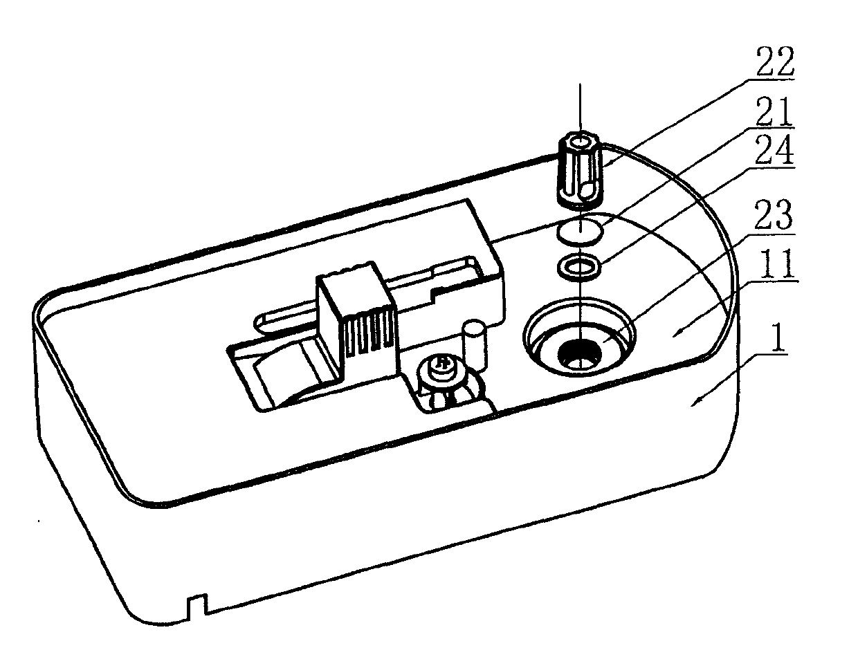
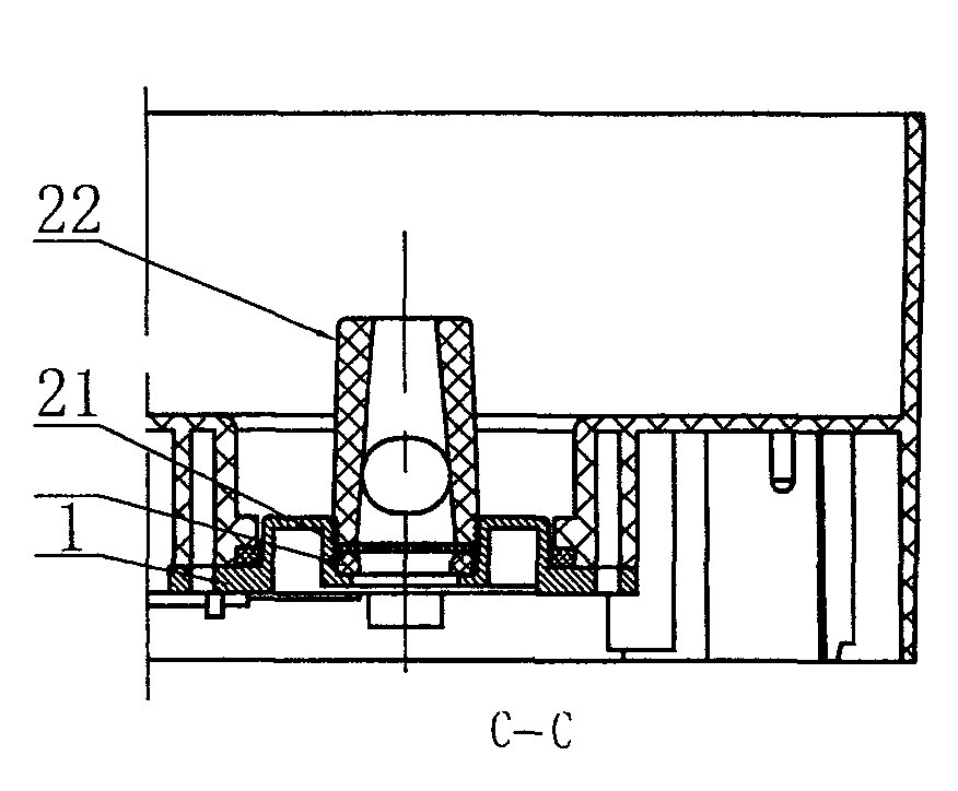
[0050] see Figures 1 to 6A As shown, the ultrasonic humidifier proposed by the embodiment of the present invention includes a machine base 1 and a water tank assembly, the water tank assembly is connected above the machine base, and the top of the machine base 1 has a water tank 11 . Described ultrasonic humidifier comprises atomizing device 2, and atomizing device 2 comprises transducer 21 (also known as oscillator) and can improve the energy-gathering cover 22 of atomization amount, and energy-gathering cover 22 is arranged on the front of transducer 21 Above, the transducer 21 is set on the machine base 1 and located in the water tank 11 ; the energy gathering cover 22 is set on the machine base 1 or the water tank assembly, and the energy gathering cover 22 of this embodiment is set on the machine base 1 .

[0051]When the embodiment of the present invention is in use, first add enough water to the water tank assembly, and after the water tank assembly is connected to the...

Embodiment approach 2

[0058] see Figure 7 to Figure 12A As shown, the basic structure, working principle and beneficial effect of the ultrasonic humidifier in the embodiment of the present invention are basically the same as those in Embodiment 1, the difference is that the energy-gathering cover 22' in the embodiment of the present invention is not installed on the core to dissipate heat chip, but mounted on chassis 1.

[0059] Specifically, a through-hole 221' is provided in the axial direction of the energy-gathering cover 22', and at least one water inlet 222' is provided at the bottom of the energy-gathering cover 22', and the water inlet 222' communicates with the through-hole 221'. Preferably, the energy gathering cover 22' is tapered, the through hole 221' is a tapered hole, the diameter of the lower end of the through hole 221' is larger than the diameter of the upper end, and the diameter of the lower end of the through hole 221' corresponds to the diameter of the transducer 21' .

[0...

Embodiment approach 3

[0065] see Figure 13 with Figure 13A As shown, the basic structure, working principle and beneficial effect of the ultrasonic humidifier in the embodiment of the present invention are basically the same as those in Embodiment 2, the difference is that the support member of the energy gathering cover 22' in the embodiment of the present invention is fixedly connected to On the machine base 1, it forms an integral structure with the machine base 1 and cannot be disassembled.

[0066] The same parts in the embodiment of the present invention as in Embodiment 2 will not be described in detail.


PUM


Abstract

The invention discloses an ultrasonic humidifier and an atomizing device thereof. The ultrasonic humidifier comprises an engine base and a water tank assembly, wherein the water tank assembly is connected above the engine base, the top of which is provided with a water tank; the ultrasonic humidifier also comprises an atomizing device consisting of an energy converter and an energy concentration cover capable of improving the atomizing quantity, wherein the energy concentration cover is arranged right above the energy converter; the energy converter is arranged on the engine base and is located in the water tank; and the energy concentration cover is arranged on the engine base or the water tank assembly. The energy concentration cover is arranged on the energy converter and can concentrate water mist generated by the energy converter so that more water mist passes through a mist outlet channel, i.e. the energy concentration cover has the function of improving the atomizing quantity and enables the humidity of indoor air to be further improved.

Description

technical field [0001] The invention relates to an ultrasonic humidifier and an atomizing device thereof. Background technique [0002] The existing ultrasonic humidifier includes a machine base and a water tank assembly, the water tank assembly is connected above the machine base, an atomizing device is installed on the machine base, and the atomizing device has a transducer. When enough water is added to the water tank assembly, the water flows into the machine base from the water tank assembly and covers the transducer, and the transducer vibrates the water in the machine base at high frequency to atomize it. At this time, under the push of the wind blown by the blower installed on the machine base, the water mist is discharged from the mist outlet and enters the air to achieve the purpose of increasing the indoor air humidity. [0003] That is to say, in the existing ultrasonic humidifier, the water mist generated by the high-frequency oscillation of the transducer is d...

Claims


Application Information

Patent Timeline
IPC IPC(8): B05B17/06B05B15/00F24F6/12F24F13/20F24F13/30F24F13/32
CPCY02B30/80Y02B30/70
Inventor 何鲁敏
Owner BEIJING YADU INDOOR ENVIRONMENT PROTECTION TECH
Why Eureka
Try Eureka