Pneumatic truss side rib bending forming mechanism

A technology of bending mechanism and moving mechanism, applied in the direction of online network, other household appliances, household appliances, etc., can solve the problems of low production efficiency, difficulty, inability to adjust pitch and height, etc., and achieve the effect of high production efficiency and forming rules.

Active Publication Date: 2010-08-04
TJK MACHINERY TIANJIN
View PDF0 Cites 29 Cited by
  • Summary
  • Abstract
  • Description
  • Claims
  • Application Information

AI Technical Summary

Problems solved by technology

The above two molding machines have the following defects: the production efficiency is low, and the pitch and he

Method used


Image

  • Pneumatic truss side rib bending forming mechanism
  • Pneumatic truss side rib bending forming mechanism
  • Pneumatic truss side rib bending forming mechanism

Examples


Embodiment Construction

[0013] Embodiments of the present invention will be further described below in conjunction with the accompanying drawings.

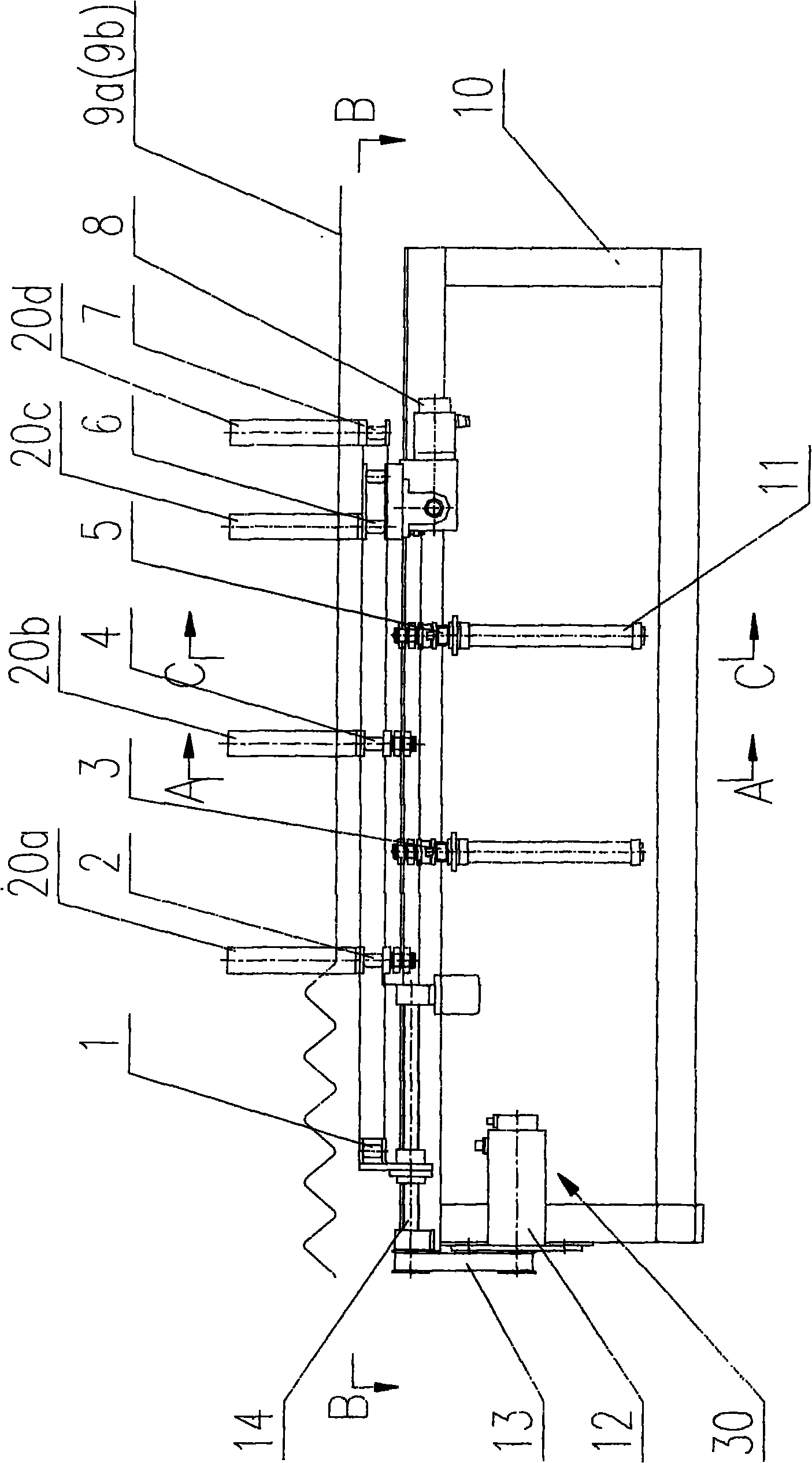
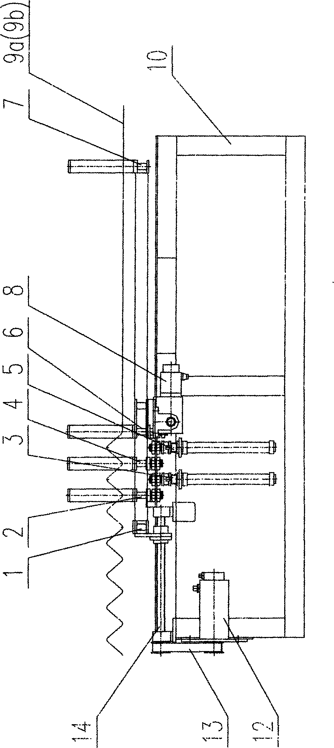
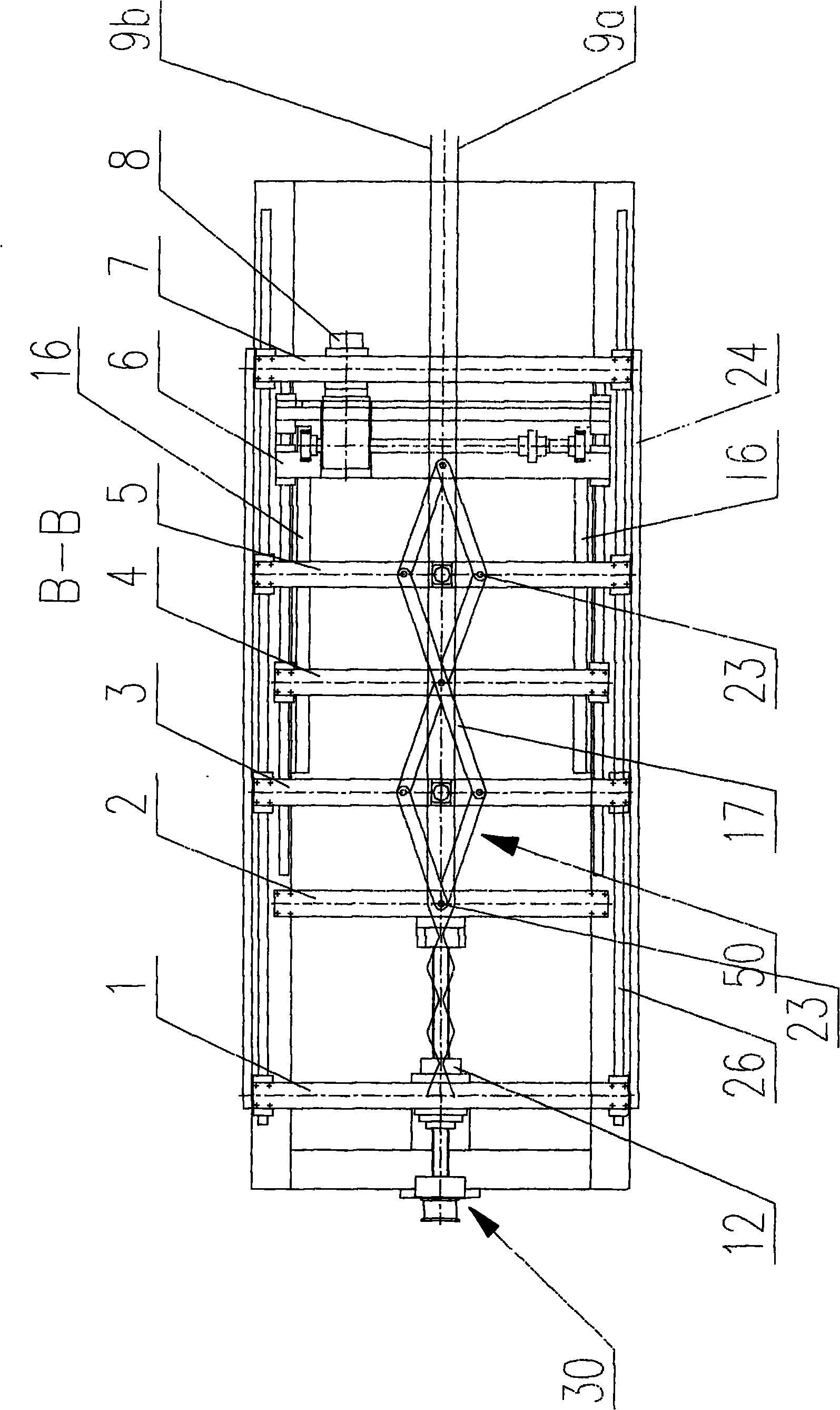
[0014] figure 1 It is a schematic diagram of the structure of the traction state of the side ribs of the present invention; figure 2 It is a structural schematic diagram of the arched state of the side reinforcement of the present invention; image 3 yes figure 1 Middle B-B sectional view, showing the upper middle of the frame, schematic diagram of the crank mechanism; Figure 4 yes figure 1 Middle A-A sectional view, showing the schematic diagram of the structure; Figure 5 yes figure 1 Middle C-C sectional view, showing the schematic diagram of the crank moving mechanism.

[0015] As shown in the figure, the present invention provides a truss pneumatic side rib bending mechanism. The truss pneumatic side rib bending mechanism includes: a frame 10 with two parallel linear guide rails 26; Side reinforcement traction mechanism 30, crank mechanism ...


PUM


Abstract

The invention discloses a pneumatic truss side rib bending forming mechanism which comprises a stand provided with a straight rail, a side rib traction mechanism, two sets of dome ejection rod mechanisms, a crank mechanism and a crank moving mechanism. The side rib traction mechanism is arranged at the left side of the stand and comprises a servo motor, a synchronous belt, a ball screw, a side rib traction cross beam, a side rib traction pressing cross beam, and a travel-adjustable cylinder and a side rib clamping device which are arranged on the side rib traction pressing cross beam. The dome ejection rod mechanisms are arranged at the lower side of a workbench surface in the side rib moving direction and comprise horizontally-arranged travel-adjustable cylinders and side rib clamping devices as well as vertically-arranged air cylinders and ejection rods. The invention has the advantages that the defects of the prior art are overcome, the production efficiency is higher, forming is regular, the truss side rib has no scratch, the bending pitch and the height of the truss side rib can be conveniently adjusted, thereby being applicable to the production of truss side rib bending wires with different pitches and heights.

Description

technical field [0001] The invention relates to a truss pneumatic side rib bending forming mechanism, in particular to a truss pneumatic side rib bending forming mechanism capable of adjusting the bending pitch and height of the truss side ribs. Background technique [0002] At present, the triangular beam truss production line used in construction or other industries needs to bend metal wires into side reinforcements of different sizes. In the prior art, there are two mechanisms for bending the side reinforcements of trusses, namely, disc bending and forming mechanisms and crawler belts. Chain bending forming mechanism. The above two molding machines have the following defects: the production efficiency is low, and the pitch and height cannot be adjusted; or although the pitch and height can be adjusted, it is very difficult and time-consuming. Contents of the invention [0003] The purpose of the present invention is to overcome the deficiencies of the above-mentioned t...

Claims


Application Information

Patent Timeline
IPC IPC(8): B21F1/00B21F23/00B21F1/04
CPCB21F27/20
Inventor 陈振东
Owner TJK MACHINERY TIANJIN
Why Eureka
Try Eureka