Fin rotating mechanism capable of dynamically measuring fin lift force
A dynamic measurement and lift technology, applied in the measurement of force, measurement device, and the use of hydrofoils to act on the surrounding water surface to reduce ship motion, etc. , to achieve the effect of dynamic decoupling and measurement
- Summary
- Abstract
- Description
- Claims
- Application Information
AI Technical Summary
Problems solved by technology
Method used
Image
Examples
specific Embodiment approach 1
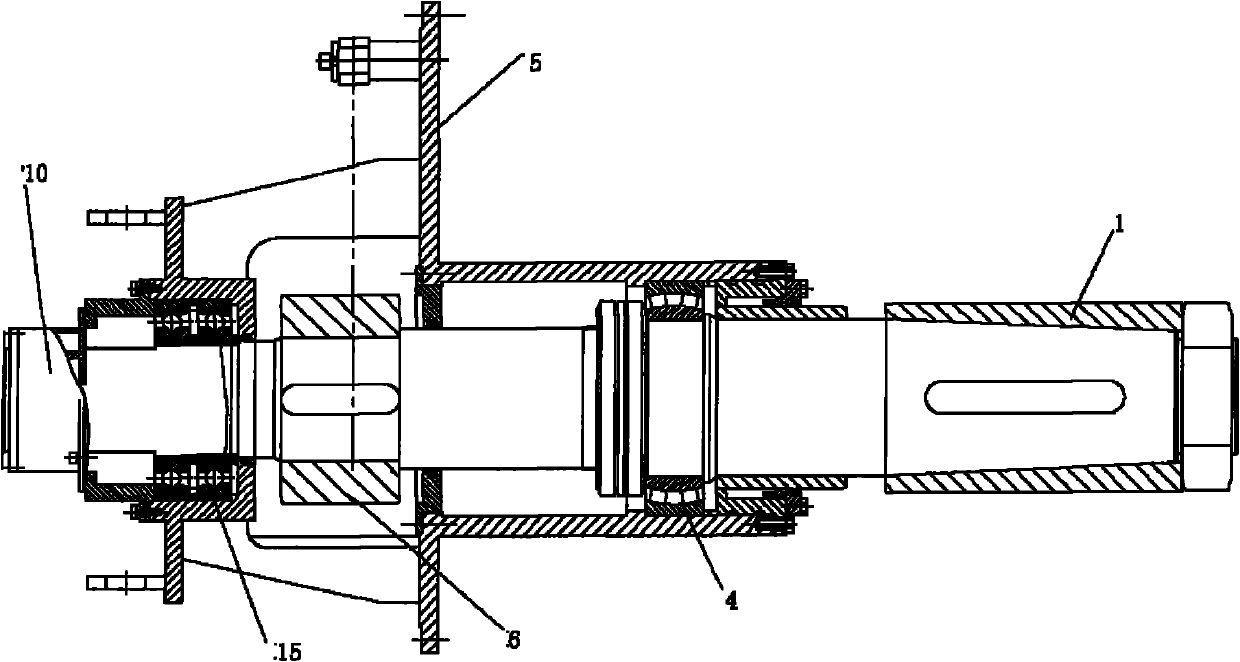
[0040] to combine Figure 4 and Figure 5 , on the basis of the traditional fixed fin stabilizer and fin rotation device, the fin shaft in the whole device adopts the hollow fin shaft 2, and a real shaft core 7 is arranged inside the fin shaft, and the shaft core 7 is connected with the fin shaft near the fin installation position The jacket is tightly connected and can rotate with the fin shaft. To fin shaft, adopt double fulcrum to fix, promptly last support bearing 15, following support bearing 4, and last support bearing 15, following support bearing 4 are all enclosed within on the fin shaft 2 overcoats, axle core 7 does not directly contact with up and down support bearing. In addition, the shaft sleeve 3 is used to fix the lower support bearing 4, and the box body 5 is welded on the hull to fix the entire mechanical structure of the fin. The rotation of the fins is figure 2 The rocker arm 6 in the drive is driven by a power mechanism.
[0041] The lift measurement s...
specific Embodiment approach 2
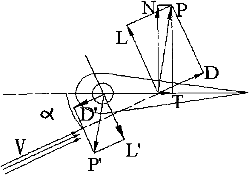
[0059] to combine Figure 6 and Figure 7 , the second embodiment of the present invention is based on the first embodiment, the lift measurement sensor adopts an installation method based on the lift characteristics of the fin.
[0060] When measuring based on the lift characteristic of the fin, a right-angled transmission rod 19 is fixedly installed at the end of the shaft core 7, and an arc-shaped gap is cut on the shell of the fin shaft in addition. shaft, while rotating with the fin shaft without touching the fin shaft. In addition, an arc-shaped induction block 20 is installed at the end of the transmission rod 19, and the arc-shaped induction block 20 can rotate with the fin shaft. Along the lift direction of the fin, a small hole is opened on the side wall of the bearing gland 18, and a fixed lift measuring sensor 21 is installed, which still adopts a non-contact displacement sensor.
[0061] After the lift measuring sensor is installed, along the Figure 6 Middle ...
PUM
 Abstract
Description
Claims
Application Information
 - R&D
- Intellectual Property
- Life Sciences
- Materials
- Tech Scout
- Unparalleled Data Quality
- Higher Quality Content
- 60% Fewer Hallucinations
Browse by: Latest US Patents, China's latest patents, Technical Efficacy Thesaurus, Application Domain, Technology Topic, Popular Technical Reports.
© 2025 PatSnap. All rights reserved.Legal|Privacy policy|Modern Slavery Act Transparency Statement|Sitemap|About US| Contact US: help@patsnap.com


