
Lens array, lens unit, LED head, exposing unit, image forming apparatus, and image reading apparatus

A technology of lens array and lens unit, applied in the field of lens array

Active Publication Date: 2010-08-04
OKI ELECTRIC IND CO LTD
View PDF7 Cites 6 Cited by
  • Summary
  • Abstract
  • Description
  • Claims
  • Application Information

AI Technical Summary

Problems solved by technology

Such removal tends to result in a wavy surface of the molded lens array
The molded lens array extends longitudinally in the direction in which the lenses are arranged, thereby causing warpage of the lens array due to the difference in shrinkage between the thin and thick portions of the lens array

Method used


Image

  • Lens array, lens unit, LED head, exposing unit, image forming apparatus, and image reading apparatus
  • Lens array, lens unit, LED head, exposing unit, image forming apparatus, and image reading apparatus
  • Lens array, lens unit, LED head, exposing unit, image forming apparatus, and image reading apparatus

Examples


no. 1 example

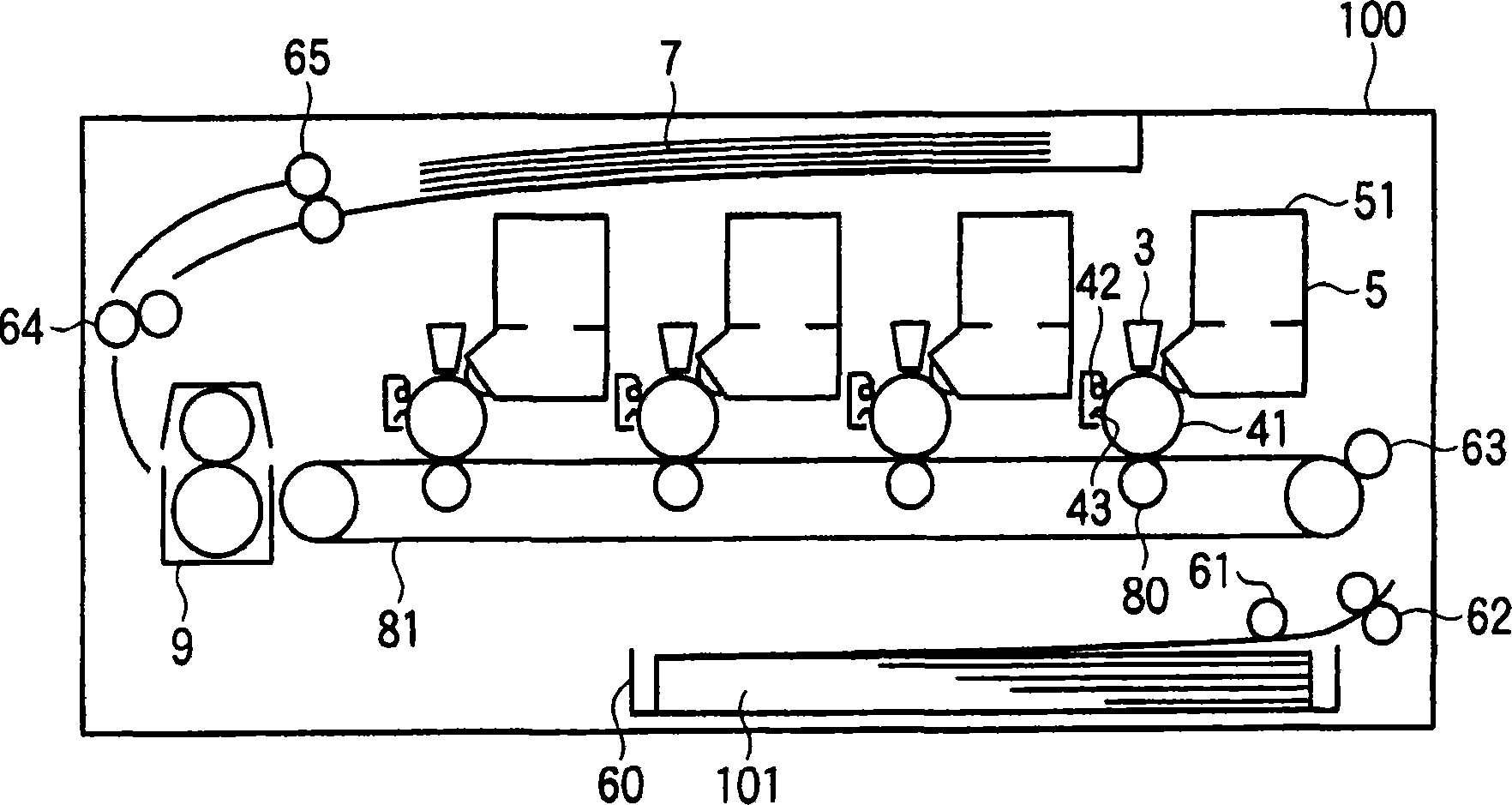
[0029] figure 1 The general configuration of the printer of the first embodiment is illustrated.

[0030] will refer to figure 1 The image forming apparatus or printer 100 of the first embodiment will be described. refer to figure 1 , the printer 100 prints an image on a medium according to image data using a toner formed of a resin containing a pigment therein. A stack of media or paper 101 is accommodated in the paper storage box 60 . Paper feed roller 61 feeds paper 101 from paper storage cassette 60 to conveyance rollers 62 and 63 , which in turn convey paper 101 on a conveyance path.

[0031] The printer 100 is an electrophotographic color printer, and includes print engines for forming yellow images, magenta images, cyan images, and black images, respectively. The print engines are arranged along the transport path of the paper 101 . Each print engine includes a photosensitive drum 41 on which an electrostatic latent image is formed.

[0032] A charging roller 42 ...

no. 2 example

[0104] The lens unit of the first embodiment has been described taking use in an image forming apparatus as an example. The lens unit of the second embodiment will be explained in terms of a lens unit included in an image reading apparatus. Figure 14 The general configuration of the image reading apparatus of the second embodiment is illustrated. Elements similar to those of the first embodiment are given the same reference numerals, and descriptions of these elements are omitted.

[0105] will refer to Figure 14 A second embodiment will be described. refer to Figure 14, the scanner 500 reads an image of a document 507 and generates image data in the form of electronic data. The scanner 500 includes an image reading head 400 , a lamp 501 , a transparent plate 502 , a rail 503 , a drive belt 505 and a motor 506 . A lamp 501 illuminates the surface of a document 507 . The image reading head 400 receives light reflected back from the surface of the document 507, and then...


PUM


Abstract

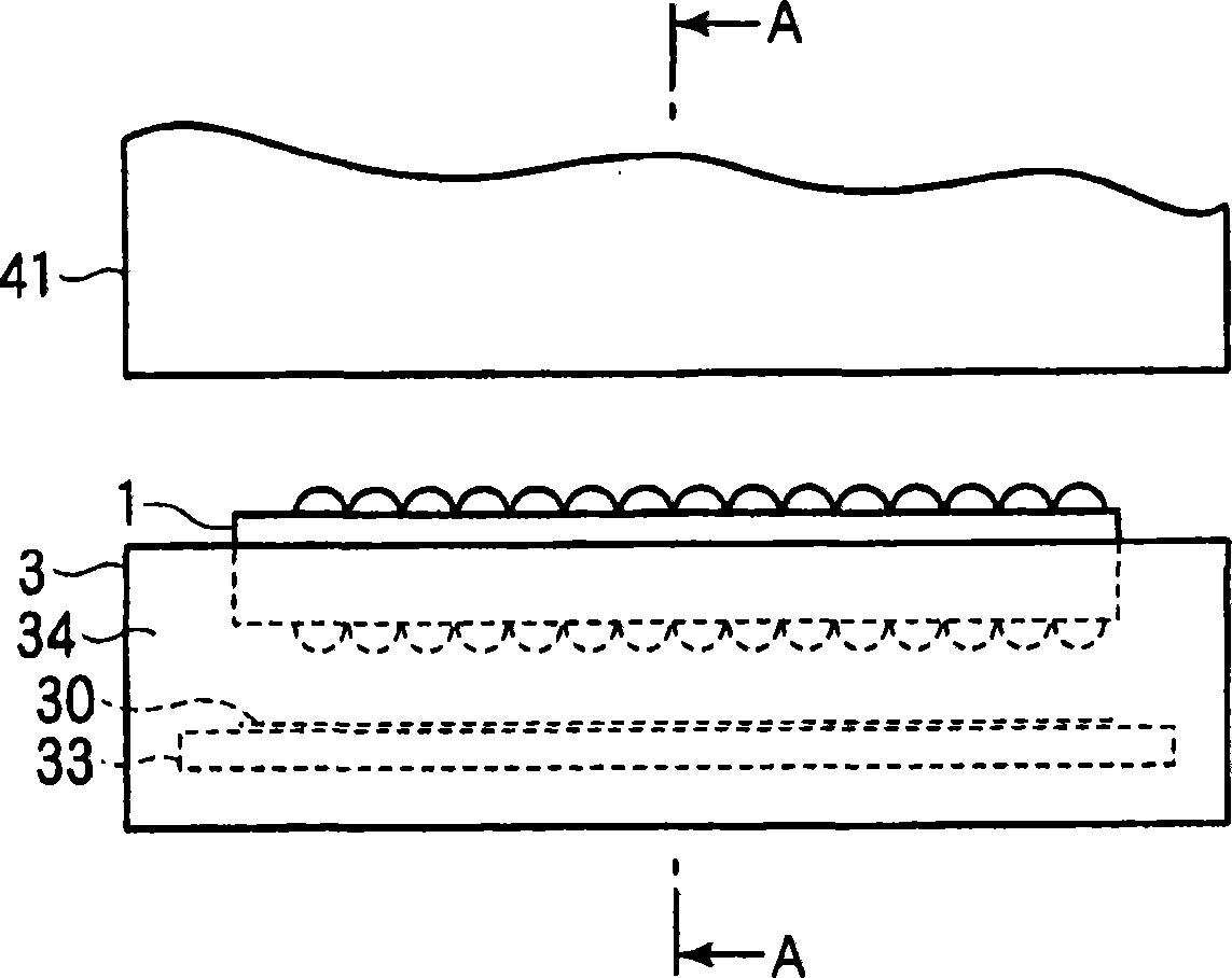
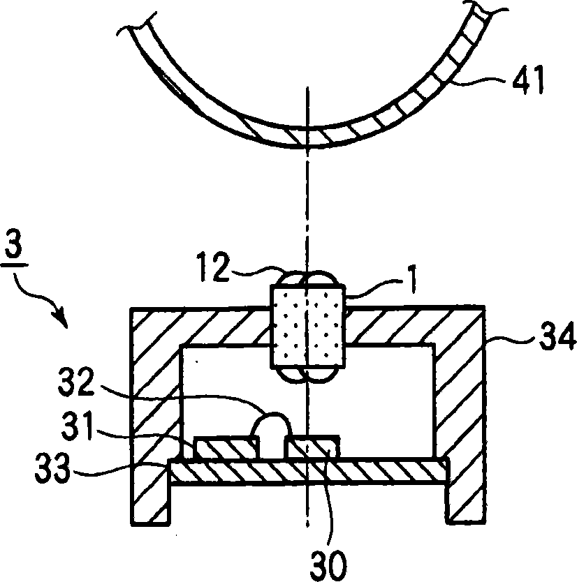
The present invention relates to a lens array, a lens unit, an LED head, an exposing unit, an image forming apparatus, and an image reading apparatus. A lens array forms an erect image of an object. The lens array includes at least one row of lens elements and at least one rib. The lens elements are aligned in a first direction perpendicular to optical axes of the lens elements having an incidence surface and an exit surface. The rib is formed on the lens array and extending in a second direction parallel to the first direction and in a third direction parallel to the optical axes further than the incidence surface and the exit surface. A lens unit includes a shielding member and the lens array assembled to the shielding member. The shielding member includes diaphragms formed therein and aligned in a first direction, and a first engagement portion. The lens array includes a second engagement portion for engaging the first engagement portion to correct deformation of the lens array.

Description

technical field [0001] The present invention relates to a lens array, a lens unit, an LED head, an exposure unit, an image forming device, and an image reading device. Background technique [0002] Electrophotographic image forming apparatuses, scanners, and facsimile machines all include an optical system capable of forming a positive image of an object having the same size as the object. For electrophotographic printers, the optical system forms a positive image of the LEDs, the same size as the light emitting diodes (LEDs), which are arranged in a line, the same size as the object. For scanners and fax machines, the optical system forms a positive image of the original document. Such optical systems use lens arrays. A conventional lens array is a group of lenses arranged in a line and forms a positive image of an object, which has the same size as the object. Certain lens arrays are formed by injection molding, thereby effectively reducing the number of parts (see Japa...

Claims


Application Information

Patent Timeline
Patent Type & Authority Applications(China)
IPC IPC(8): G02B3/00B41J2/45G03G15/04
CPCB41J2/451G02B3/0056G03G15/326G02B3/0075G03G15/04054
Inventor 山村明宏
Owner OKI ELECTRIC IND CO LTD
Learn More