Electronic status detection device

A state detection and equipment technology, applied in electrical components, circuits, electrical switches, etc., to solve complex and expensive problems

Inactive Publication Date: 2010-08-04
HUF HULSBECK & FURST GMBH & CO KG
View PDF1 Cites 3 Cited by
  • Summary
  • Abstract
  • Description
  • Claims
  • Application Information

AI Technical Summary

Problems solved by technology

This solution is relatively complex and expensive

Method used


Image

  • Electronic status detection device
  • Electronic status detection device
  • Electronic status detection device

Examples


Embodiment Construction

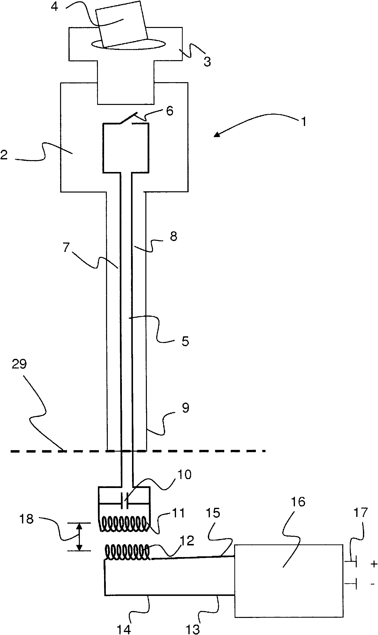
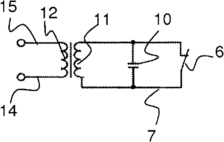
[0029] figure 1 A buckle 1 designed according to the invention is shown in a schematic side view. The buckle 1 has a housing 2 which houses the mechanical parts of the buckle (not shown here). The buckle 1 has a belt clip 3 inserted therein, on which a strap 4 is pivoted. The housing 2 also partially accommodates a passive resonant circuit 5 . In the embodiment shown, the housing 2 contains the switch 6 and the parts of the first electrical line 7 and the second electrical line 8 inside the housing 2 . A buckle handle 9 protrudes downward from the housing 2 . The buckle handle 9 is then fastened to the vehicle 29 , in another embodiment the mechanical fixing of the buckle handle 9 can be dispensed with at this junction. Parallel to the buckle handle 9, the first wire 7 and the second wire 8 are routed downwards to where the other elements of the passive resonant circuit 5 are located. In this case, the passive resonant circuit 5 has a capacitor 10 and a coil 11 arranged p...


PUM


Abstract

The invention relates to an electronic status detection device for wireless detection of at least one status of an apparatus, wherein the status detection device comprises at least two resonant circuits (5, 13), of which at least one resonant circuit (13) is active and one resonant circuit (5) is passive, wherein the active resonant circuit (13) comprises at least one control device (16). A status detection device such as this makes it possible, for example, to reliably detect the presence or the absence of belt clips in safety belt locks.

Description

technical field [0001] The invention relates to an electrical state detection device for a vehicle for wirelessly detecting at least one state of a device. Furthermore, the invention relates to a motor vehicle having at least one electrical state detection device. The invention serves to detect the state of at least one tool or a piece of equipment in a vehicle, and is used in particular in the automotive sector. Background technique [0002] In modern vehicles there is an increasing need to detect components, tools, units or devices as well as their status and functions. Some of these aspects are subject to legal regulations, for example, and also arise from the purpose of improving the safety of motorists or increasing comfort. Thus, in modern vehicles, for example, when starting a motor vehicle, it is detected whether the doors are closed properly, whether the seat belt is fastened and / or the low pressure of the brake pedal. Furthermore, seat occupancy recognition of t...

Claims


Application Information

Patent Timeline
Patent Type & Authority Applications(China)
IPC IPC(8): H01H9/16H03K17/18H04B5/00
CPCH01H9/168H01H9/167H04B5/0075
Inventor 斯文·希尔德马丁·施奈德斯特凡·里夫尔斯丹尼尔·延德里察
Owner HUF HULSBECK & FURST GMBH & CO KG
Why Eureka
Try Eureka