Supercharge Your Innovation With Domain-Expert AI Agents!

Automatic lug shaping mold

An ear mold and automatic technology, which is applied in the direction of electrical components, circuits, battery pack components, etc., can solve the problems of easily damaged ears, low efficiency, and large labor consumption, etc., to achieve fast sorting, good sorting effect, and high work efficiency Effect

Active Publication Date: 2010-08-11
ZHEJIANG HAIYUE AUTOMATIC MACHINERY
View PDF4 Cites 17 Cited by
  • Summary
  • Abstract
  • Description
  • Claims
  • Application Information

AI Technical Summary

Problems solved by technology

However, during the clamping process, the arrangement of the lugs of each plate is uneven. The traditional method of arranging the lugs is as follows: figure 1 As shown, place an iron bar 01 between the positive and negative lugs of one pole group, which is equivalent to the standard lug spacing, and then the operator holds the iron piece 02 and knocks the outside of the lug so that the positive and negative lugs are aligned with the iron. At this time, the two rows of pole ears in the pole group are very neat. Although the expected effect is achieved, this method is inefficient, consumes a lot of labor, and is easy to damage during the knocking process. tabs, thus affecting product quality
In the patent No. "200420054262.8", the patent titled "Organizer for Arranging the Tabs of Electrode Groups" discloses a device for arranging the tabs, including a body, which is provided with a wedge-shaped arrangement matching the tabs. There are positioning strips between the finishing grooves that are equivalent to the spacing of the tabs. When in use, the body is covered on the pole group, the finishing groove is aligned with the tabs and the body is knocked, and the wedge-shaped structure is used to make the tabs align with the axial direction of the finishing groove. The center line is close to achieve the purpose of finishing. Although this scheme improves the efficiency of ear adjustment, the wedge-shaped surface of the arrangement groove is inclined to the side of the ear. During the ear adjustment process, the percussion force of the operator on the body will produce The force in two directions, of which only the force perpendicular to the side of the ear is effective, and the finishing groove and the positioning bar are fixed structures, so that the artificial percussion force cannot be fully utilized, and the ear adjustment effect is poor

Method used


Image

  • Automatic lug shaping mold
  • Automatic lug shaping mold
  • Automatic lug shaping mold

Examples


Embodiment Construction

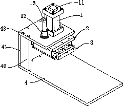
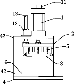
[0021] like figure 2 , image 3 As shown, the present invention is an automatic ear mould, comprising a mold base, a shaping mechanism 3 and a push plate mechanism 2 arranged above the shaping mechanism 3, the shaping mechanism 3 and the pushing plate mechanism 2 are connected by an elastic mechanism 5, and the shaping A shaping groove 36 that can move laterally is arranged in the mechanism 3, and the pushing plate mechanism 2 pushes the shaping mechanism 3 to move through the elastic mechanism 5 so that the product lug enters the shaping groove 36, and the pushing plate mechanism 2 acts on the shaping mechanism 3 when it goes down. The shaping groove 36 shrinks laterally to realize tab arrangement.

[0022] like Figure 4 to Figure 7 As shown, the preferred structure is as follows: the shaping mechanism 3 is a fence-like structure formed by a plurality of shaping units connected in series through fixing strips 31 and pin shafts 32. The movable clip 34, the shaping groove ...


PUM


Abstract

The invention discloses an automatic lug shaping mold, which comprises a mold base, a shaping mechanism and a push plate mechanism arranged above the shaping mechanism. The shaping mechanism and the push plate mechanism are connected through an elastic mechanism, wherein shaping slots which can move horizontally are arranged in the shaping mechanism, and the push plate mechanism pushes the shaping mechanism to move through the elastic mechanism so that product lugs can enter the shaping slots, and acts on the shaping mechanism during downward movement, so that the shaping slots can shrink horizontally, thereby realizing lug arrangement. The invention can realize rapid lug arrangement without damaging the lugs, and has the advantages of high efficiency and good arrangement effect.

Description

technical field [0001] The invention relates to an auxiliary processing mold for a storage battery, in particular to an automatic ear mold for arranging battery electrode groups in storage battery production. Background technique [0002] In the process of producing batteries at present, the positive and negative plates are usually clamped into several battery electrode groups by using an assembly fixture. However, during the clamping process, the arrangement of the lugs of each plate is uneven. The traditional method of arranging the lugs is as follows: figure 1 As shown, place an iron bar 01 between the positive and negative lugs of one pole group, which is equivalent to the standard lug spacing, and then the operator holds the iron piece 02 and knocks the outside of the lug so that the positive and negative lugs are aligned with the iron. At this time, the two rows of pole ears in the pole group are very neat. Although the expected effect is achieved, this method is inef...

Claims


Application Information

Patent Timeline
IPC IPC(8): H01M2/26B21D3/00H01M50/533H01M50/536
CPCY02E60/10
Inventor 陈义忠
Owner ZHEJIANG HAIYUE AUTOMATIC MACHINERY
Features
  • R&D
  • Intellectual Property
  • Life Sciences
  • Materials
  • Tech Scout
  • Unparalleled Data Quality
  • Higher Quality Content
  • 60% Fewer Hallucinations
Learn More