This helps you quickly interpret patents by identifying the three key elements:
Problems solved by technology
Method used
Benefits of technology
Problems solved by technology
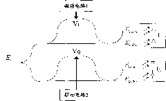
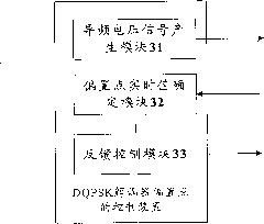
[0007] The main purpose of the present invention is to provide a method and device for controlling the bias point of a DQPSK demodulator to solve the problem that related technologies are easily affected by the external environment, have poor reliability, and can only lock the bias point to π / 4 and - π / 4, the problem of not being able to lock the bias point to other desired values
Method used
Image
Click on the blue label to locate the original text in one second.
Reading with bidirectional positioning of images and text.
Examples
Embodiment 1
[0078] Figure 7 It is a structural diagram of a bias point control system of a DQPSK demodulator according to Embodiment 1 of the present invention. like Figure 7 As shown, in this preferred embodiment:
[0079] Input optical signal E i After passing through the 3dB coupler 100, it is divided into two signals, the I channel and the Q channel. The I light is divided into two light paths through a 3dB coupler 101A, which respectively pass through the L I +ΔL I and L I The optical path, and after π / 4 phase change, and then through 102A coupling output E I,cos ,E I,des . E. I,cos ,E I,des Then through the balanced receiver 103A, the current i I . Similarly, the light of Q path is divided into two paths of light through a 3dB coupler 101B, and passes through L Q +ΔL Q and L Q The optical path, and -π / 4 phase change, and then through 102B coupling output E Q,cos ,E Q,des . E. Q,cos ,E Q,des Then through the balanced receiver 103B, the current i Q .
[0080] T...
Embodiment 2
[0082] Figure 8 It is a flow chart of bias point control of the DQPSK demodulator according to Embodiment 2 of the present invention. In this embodiment, a digital algorithm employed within the DSP controls the bias point of the DQPSK demodulator. The specific process is as follows:
[0083] S801. Acquiring the current value i of the balanced receiver from the high-speed and high-precision AD I i Q
[0084] S802, use the digital filter algorithm to obtain the current value i I i Q The magnitude values of the DC component, the first harmonic component and the second harmonic component;
[0085] S803. Jointly solve the equation to obtain the current offset point position θ I , θ Q ;
[0086] S804. Adjust the bias voltage so that θ I = π / 4, θ Q =7π / 4, at this time the demodulator is locked on the correct bias point;
[0087] After a delay for a period of time, repeat S801-S804.
[0088] From the above description, it can be seen that the present invention achieves...
PUM
Abstract
The invention discloses bias point control method and device of a DQPSK demodulator. The method comprises the following steps of: respectively applying a first bias voltage and a second bias voltage to an path I of the DQPSK demodulator and respectively applying the same pilot-frequency voltage signals to the path I and a path Q; filtering the differential current signal of the path I of the DQPSK demodulatorand determining the real-time value theta I of the bias point of the path I, and filtering the differential current signal of the path Q of the DQPSK demodulator and determining the real-time value theta Q of the path Q, wherein the differential current signal of the path I and the differential current signal of the path Q are both collected by a balanced receiver; and carrying out feedback control on the first bias voltage according to the theta I and carrying out feedback control on the second bias voltage according to the theta Q until the theta I reaches the expected value of the bias point of the path I and the theta Q reaches the expected value of the bias point of the path Q. By adopting the technical scheme, the invention can lock the expected values at any bias points, is convenient for the realization of digitization and is not easy to be influenced by external environment.
Description
technical field [0001] The invention relates to the field of optical communication, in particular to a method and device for controlling a bias point of a DQPSK demodulator. Background technique [0002] DQPSK (differential quadrature phase shift keying) is the differential quadrature phase shift keying modulation method. In recent years, with the improvement of the speed and capacity of the optical transmission system, the optical phase modulation method represented by DQPSK has attracted more and more attention from the industry. [0003] figure 1 is a schematic structural diagram of a DQPSK demodulator according to the prior art. like figure 1 As shown, the input optical carrier can be expressed as: where E is the field strength, ω 0 is the angular frequency of the optical carrier, is the modulation phase. The principle of DQPSK demodulator modulation is: encode the information to be transmitted in the differential phase of continuous optical bits, using expres...
Claims
Application Information
Patent Timeline
Application Date:The date an application was filed.
Publication Date:The date a patent or application was officially published.
First Publication Date:The earliest publication date of a patent with the same application number.
Issue Date:Publication date of the patent grant document.
PCT Entry Date:The Entry date of PCT National Phase.
Estimated Expiry Date:The statutory expiry date of a patent right according to the Patent Law, and it is the longest term of protection that the patent right can achieve without the termination of the patent right due to other reasons(Term extension factor has been taken into account ).
Invalid Date:Actual expiry date is based on effective date or publication date of legal transaction data of invalid patent.

