Accurate-positioning image-distortion-free X-ray digital imaging device and imaging method

A technology of accurate positioning and image distortion, applied in measuring devices, X/γ/cosmic radiation measurement, radiation measurement, etc., can solve the problems of inability to scan through perspective, weak light and shadow of the fluorescent screen, X-ray radiation damage, etc., so as to facilitate comparative diagnosis , realize remote diagnosis and reduce the effect of radiation dose

Inactive Publication Date: 2009-11-25
DANDONG DONGFANG MEASUREMENT&CONTROL TECHCO
View PDF1 Cites 9 Cited by
  • Summary
  • Abstract
  • Description
  • Claims
  • Application Information

AI Technical Summary

Problems solved by technology

However, the structure of this method is complicated, and the light and shadow on the fluorescent screen are weak, and after another optical-digital conversion, it is easy to lose some weak contrast information, resulting in misdiagnosis and missed diagnosis by doctors.
The other is to use a plate detector to directly shoot or a line detector to scan and shoot. This method is that the detector converts the intensity of different regions of the received X-rays into electronic signals and transmits them to the host, finally forming a digital image. , but there is no specific algorithm for converting the detector signal of the point-by-point area into the gray value of the image, and the accuracy and resolution of the detector are very high, making the cost expensive
[0004] And there is still a disadvantage in the above two methods, that is, it is impossible to perform fluoroscopy scanning on a specific local area, so that some areas of the patient that do not need fluoroscopy scanning have also received X-ray radiation damage.

Method used


Image

  • Accurate-positioning image-distortion-free X-ray digital imaging device and imaging method
  • Accurate-positioning image-distortion-free X-ray digital imaging device and imaging method
  • Accurate-positioning image-distortion-free X-ray digital imaging device and imaging method

Examples


Embodiment Construction

[0023] The device structure and imaging method of the present invention are described in conjunction with the accompanying drawings.

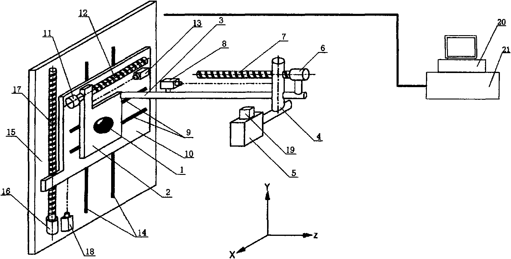
[0024] The device structure of the present invention is as figure 1 Shown:

[0025] The detector 1 is placed on the detector base 2, and a long pole 3 is installed at a distance of 50 cm from the detector. The other end of the long pole 3 is equipped with a crossbar 4, and the X-ray source 5 is fixed on the crossbar 4. The ray source 5 is provided with collimating facilities to ensure that the X-rays emitted by the X-ray source 5 exit in the form of a single beam and face the detector 1 . And the cross bar 4 can slide on the long bar 3, thereby adjusting the distance from the X-ray source to the detector. During the sliding process of the crossbar, the X-ray source is always kept facing the detector, and the adjustable distance from the X-ray source to the detector ranges from 300mm to 700mm. A Z-direction stepping motor 6 is fixed on the l...


PUM


Abstract

The invention provides an accurate-positioning image-distortion-free X-ray digital imaging device and an imaging method. An X-direction displacement sensor and a stepper motor are arranged on a movable plate; a Y-direction displacement sensor and another stepper motor are arranged on a fixed plate; a detector is arranged on the movable plate; a long rod is arranged on a detector base; a cross rod is arranged on the long rod; an X-ray source is fixed on the cross rod; a digital optical camera is arranged on the X-ray source; and a Z-direction stepper motor and a displacement sensor are arranged on the long rod. The imaging method comprises that: the distance of the detector is regulated through the stepper motor on the long rod; the stepper motors on the movable plate and the fixed plate are regulated to allow the detector to scan from a starting point in the position of a perspective area to an ending point; the detector transmits measured electronic signals to a host computer; and the host computer transforms the electronic signals into gray values of regional color blocks in digital images. The invention has the advantages of fast imaging, capability of carrying out various types of digital processing on images and realizing remote diagnosis, perspective scan in local regions and reduction in damage of rays to human body.

Description

Technical field: [0001] The invention relates to a medical device, specifically an X-ray digital imaging device. Background technique: [0002] X-ray images account for 70% of all medical images in hospitals. X-ray fluoroscopy machines are necessary routine equipment in hospitals, and X-ray fluoroscopy images have also become an important basis for medical diagnosis. However, since the current conventional X-ray fluoroscopy machines mostly use flat screens or line detectors to move and scan images to form images, while the X-ray source uses the form of point sources. In this way, the image will be distorted, such as image 3 : What the doctor needs for diagnosis is the fluoroscopic image in the form shown by the dotted line, but the actual fluoroscopic image obtained is formed by the projection of X-rays in the form of solid lines. In addition, the perspective patient's body has an irregular section. Therefore, it can be seen from the figure that the farther the area is fro...

Claims


Application Information

Patent Timeline
Patent Type & Authority Applications(China)
IPC IPC(8): A61B6/02G01T1/161
Inventor 张伟龚亚林侯朝勤宋青锋李岩峰肖宪东吴志强佟超赵龙尹兆余于海明魏晓云张剑亮刘晓玲
Owner DANDONG DONGFANG MEASUREMENT&CONTROL TECHCO
Why Eureka
Try Eureka