Positioning method and structure of cooker lid

A technology of positioning structure and positioning method, applied in pressure cookers and other directions, can solve the problems of easy aging and jamming, dirt breeding bacteria and other problems

Inactive Publication Date: 2010-08-18
FOSHAN FUSHIBAO ELECTRICAL APPLIANCE TECH
View PDF6 Cites 2 Cited by
  • Summary
  • Abstract
  • Description
  • Claims
  • Application Information

AI Technical Summary

Problems solved by technology

However, the stop block of this technical solution is arranged on the inner side of the hinged portion of the lid handle and the pot body, and the edge of the pot cover is inserted into the gap cavity between the stop block and the cover handle. After reaching the vertical state, the pot cover part in the gap cavity between the stop block and the cover handle becomes the lowest point of the entire pot cover, and the condensed water and other sundries in the pot cover will follow the edge of the pot cover. dripping into the gap cavity between the stop block and the cover handle, resulting in the accumulation of dirt and breeding bacteria; secondly, the movable block and the springs and other components set therein are also prone to aging during use. block

Method used


Image

  • Positioning method and structure of cooker lid
  • Positioning method and structure of cooker lid
  • Positioning method and structure of cooker lid

Examples


Embodiment 1

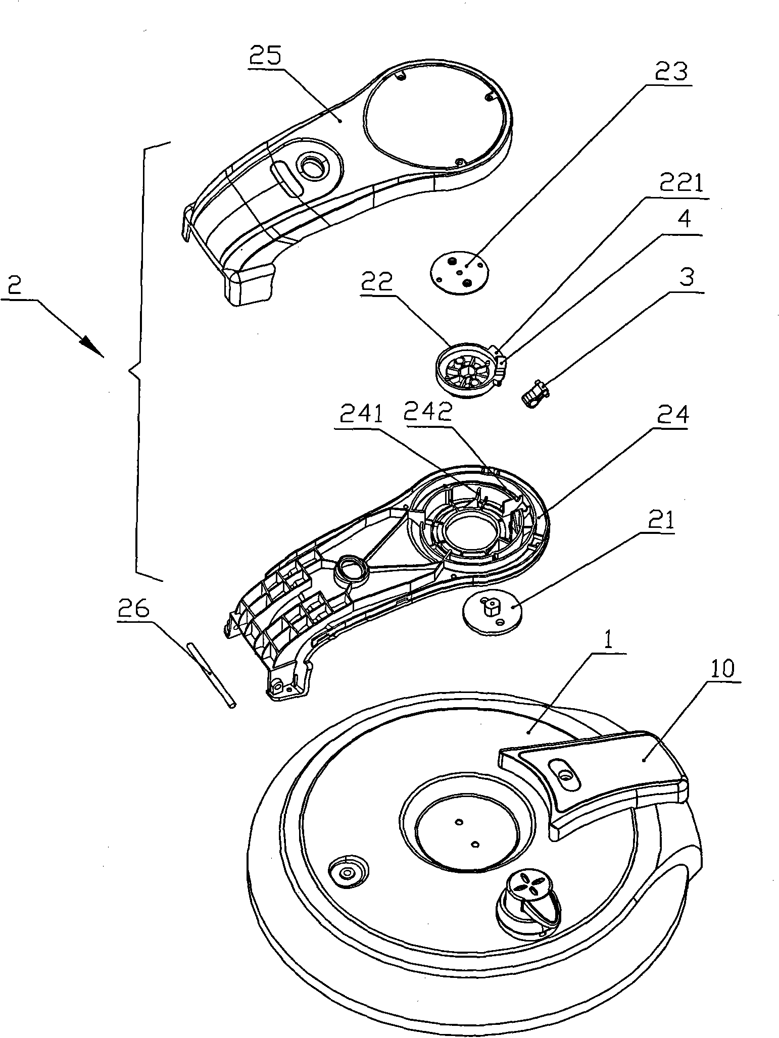
[0034] Such as figure 1 , figure 2 , image 3 , Figure 4 and Figure 5 As shown, the positioning structure of the pot cover includes a pot cover 1, a pot cover support arm 2 and a pendulum 3.

[0035] Described pot cover support arm 2 is rotatably fixed on the pot body (not shown in the figure) by hinge shaft 26. The pot cover support arm 2 includes an upper support arm 25 and a lower support arm 24, and the upper support arm 25 and the lower support arm 24 are buckled up and down;

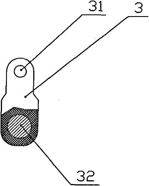
[0036] The pendulum 3 is accommodated in the space between the upper support arm 25 and the lower support arm 24 . The pendulum 3 is made of plastic, and the rotating shafts 31 provided on both sides of the top end are rotatably positioned in the slot 242 on the lower support arm 24 . Wherein the pendulum 3 is gourd-shaped, the cross-section of the top end is smaller than the cross-section of the tail end, and a metal bead 32 is accommodated in the tail end, thereby increasing the swinging...

Embodiment 2

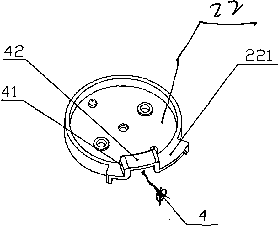
[0044] Such as Figure 6 and Figure 7 As shown, the difference from Embodiment 1 is that the top end of the pendulum 3 is rotatably positioned on the upper surface of the pot cover 1, and the pot cover 1 is connected to the pot cover support arm 2. On the pot body 11; wherein a pit that can accommodate the pendulum 3 is set on the upper surface of the pot cover 1, a slot is set in the pit, and the rotating shaft 31 provided on both sides of the pendulum 3 can It is rotatably positioned in the card slot; as for the rotatable positioning method of the rotating shaft 31 in the card slot, various conventional technical solutions such as auxiliary cover plate and chute structure can be used. Secondly, a positioning groove 4 adapted to the pendulum 3 is provided on the support arm 2 of the pot lid, wherein the notch of the positioning groove 4 faces the pendulum 3 . When the pot cover 1 is in the horizontal position, the pendulum 3 is accommodated in the groove on the top of the ...


PUM


Abstract

The invention discloses a positioning structure of a rice cooker lid, which comprises a cooker lid and a cooker lid supporting arm. The cooker lid is rotatably and fixedly connected to the lower side of the cooker lid supporting arm. The positioning structure of a rice cooker lid is characterized in that a pendulum is used as a basic positioning device and arranged in a suitable position between the cooker lid and the cooker lid supporting arm, a metal body is contained at the tail part of the pendulum, the tail part of the pendulum is separated from a positioning groove when the cooker lid and the cooker lid supporting arm are in horizontal positions, and the tail part of the pendulum swings into the positioning groove under the action of weight when the cooker lid and the cooker lid supporting arm are in vertical positions so that the cooker lid is limited from rotating left and right. The technical scheme is suitable for positioning structures of various cooker lids.

Description

technical field [0001] The invention relates to the technical field of household appliances, in particular to a positioning structure of a pot cover of a rice cooker. Background technique [0002] The rice cooker generally comprises a pot cover and a pot body. Wherein the pot body is at least the outer shell, and the outer pot or the inner pot is accommodated in the outer pot; the outer pot is provided with a heater; the pot lid covers the upper opening of the inner pot and seals the mouth of the inner pot through a sealing ring [0003] In order to facilitate the placement of the lid of the rice cooker, there have been plans to provide a lid handle on the lid. The lid can be rotated and fixed on the lid handle, and the lid handle is rotatably fixed to the rice cooker through a hinge mechanism. on the body of the pot. In this way, when the pot cover is opened, the pot cover turns over with the pot cover handle and is fixed on the pot body, so that there is no need to worry...

Claims


Application Information

Patent Timeline
IPC IPC(8): A47J27/09
Inventor 陆社本
Owner FOSHAN FUSHIBAO ELECTRICAL APPLIANCE TECH
Why Eureka
Try Eureka