Electromechanical transducer device

一种感测装置、机电式的技术,应用在机械控制装置、传动装置控制、控制机构等方向,能够解决不利等问题

Active Publication Date: 2010-08-18
ECS ENGINEERED CONTROL SYST
View PDF7 Cites 4 Cited by
  • Summary
  • Abstract
  • Description
  • Claims
  • Application Information

AI Technical Summary

Problems solved by technology

[0006] A disadvantage of these known sensing devices is that many Hall sensors are used and the circuit board has a considerable area associated therewith
This is especially disadvantageous when the various gearshift or selector devices have selector levers of different lengths

Method used


Image

  • Electromechanical transducer device
  • Electromechanical transducer device
  • Electromechanical transducer device

Examples


Embodiment Construction

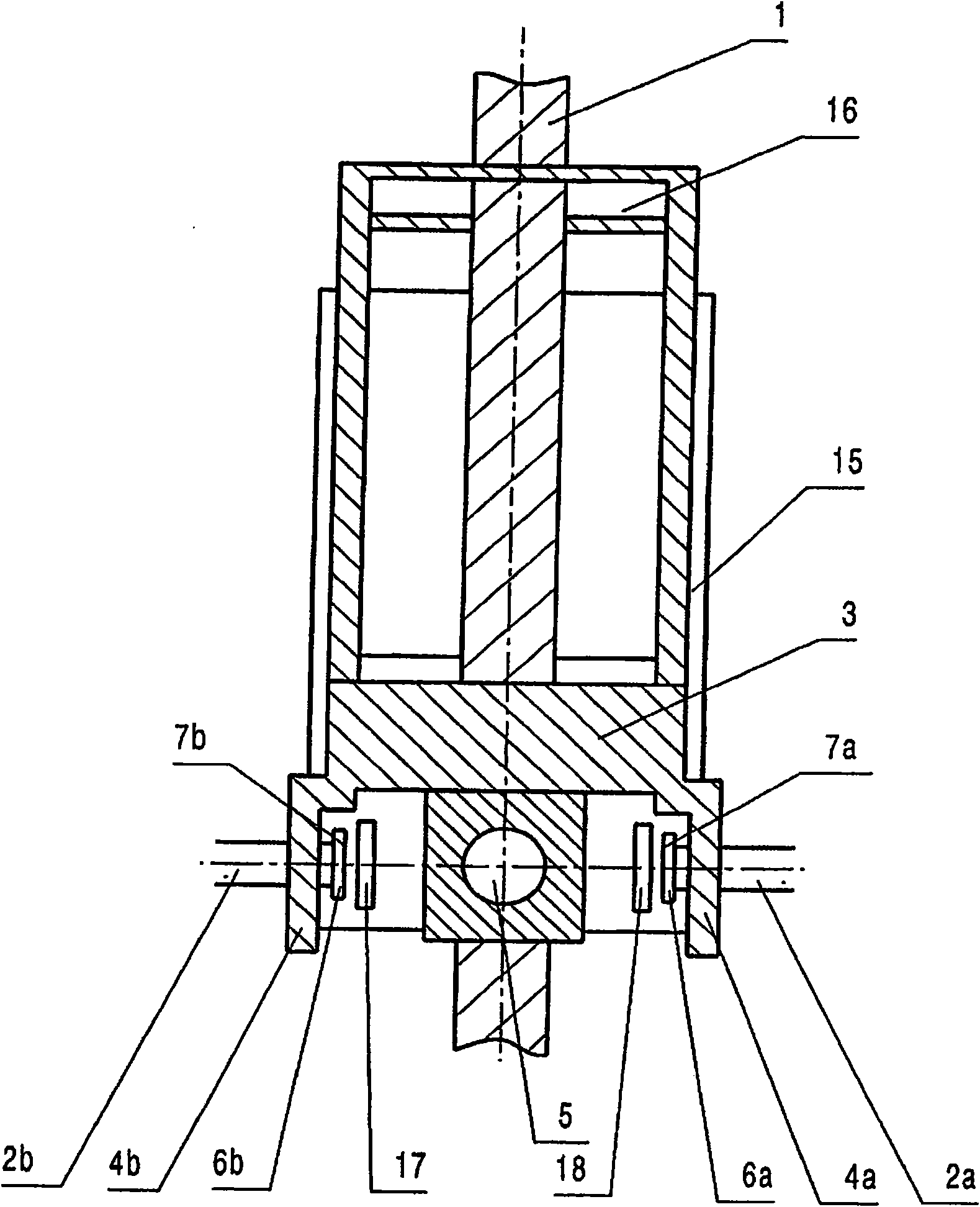
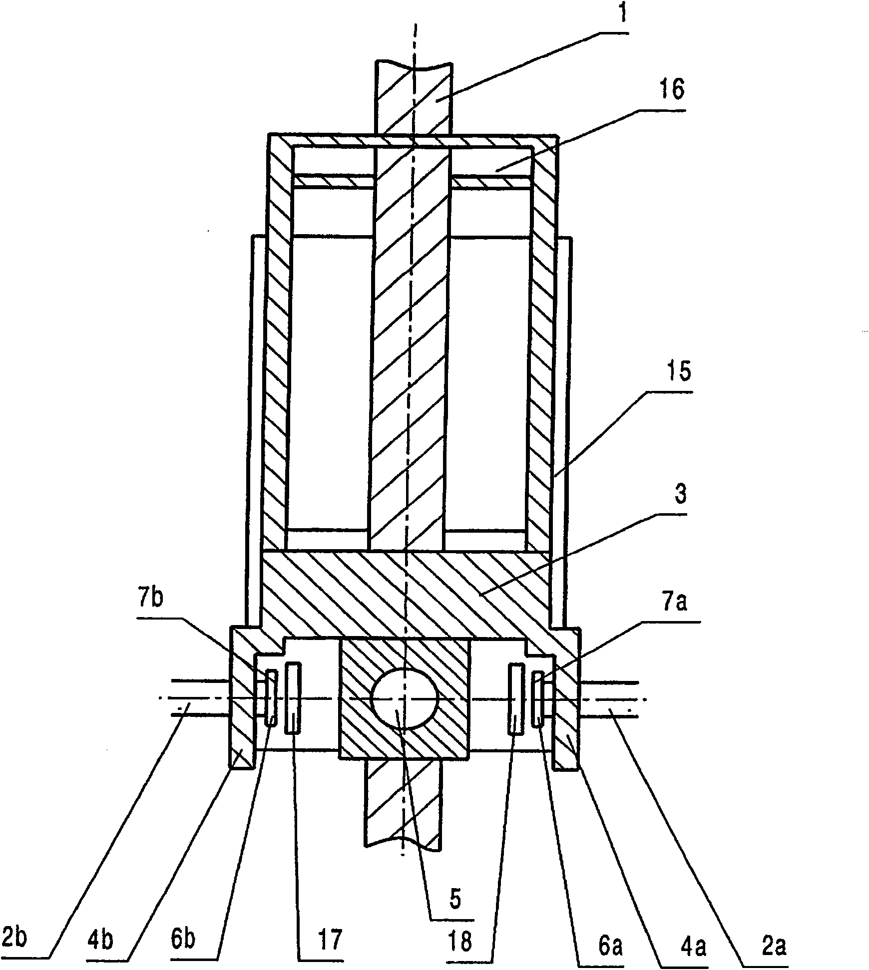
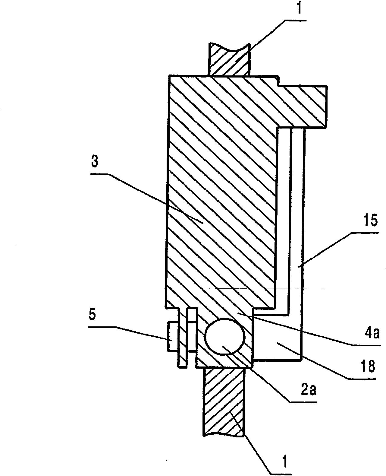
[0040] 1 to 3 illustrate a first design of the automatic transmission of the invention for a motor vehicle, wherein the shift and selector lever 1 can be positioned in two different positions with respect to the first shaft 2a, 2b and with respect to the second shaft 5. Supported for swinging in the direction. The two different pivot planes roughly define a manual shift mode and a so-called automatic channel, in which the lever can be shifted into gears P, N, R, S. The rod 1 extends through an elongated hole 16 arranged on the upper section of the suspension device 3, wherein the suspension device can be designed as a shift lever holder and has an elongated hole 16 whose longitudinal extension is parallel to First pivot axis 2a, 2b.

[0041] The suspension device 3 or the selector lever holder has bearing lugs 4a, 4b on both side ends on its lower section, which receive the free end sections of the bearing bolts 2a, 2b, whereby The suspension device 3 can be pivoted overall ...


PUM


Abstract

An electromechanical transducer device for controlling at least one function of a transmission or drive of a vehicle that is disposed spatially at a distance, comprising a lever (1) that can be pivotally actuated about at least one first axis (2a, 2b) and which is mechanically decoupled from the transmission or drive. Said lever is supported by means of a suspension (3) on the first axis (2a, 2b), wherein the axis (2a, 2b) comprises at least one first component (6a, 6b) of a magnetic rotational angle sensor system (6a, 6b, 7a, 7b) at an axial end section and for the direct detection of the angular position or the rotational movement of the lever (1) interacts with a second component (7a, 7b) of the rotational angle sensor system, said second component being arranged on the suspension (3) opposite of the end section of the axis (2a, 2b), wherein the axial end section is located within the suspension (3), wherein a circuit board (15) accommodating the rotational angel sensors (7a, 7b) is arranged on the suspension (3) and the circuit board (15) comprises at least on flange-like extension (17, 18) protruding from the circuit board plane.

Description

technical field [0001] The invention relates to an electromechanical sensor device for controlling at least one function of a transmission or drive of a motor vehicle which is arranged spatially remote from the sensor. Background technique [0002] Such electromechanical sensing devices for controlling functions of a motor vehicle transmission or of a motor vehicle drive, such as a selector lever, which can be shifted into various gear positions are known in the prior art middle. In selector levers of gearshift transmissions or automatic transmissions, it is common to detect the different gear positions of the selector lever, for example the gear positions P, N, R, S, by means of many different Hall sensors. It is provided here that a circuit board is arranged parallel to the pivoting plane of the lever, which circuit board is equipped with individual Hall sensors spaced apart from one another. [0003] The arrangement of the Hall sensors is designed in such a way that eac...

Claims


Application Information

Patent Timeline
Patent Type & Authority Applications(China)
IPC IPC(8): F16H59/10F16H59/04G05G9/047
CPCG05G1/04F16H59/105G05G2009/04755F16H59/0204F16H59/044
Inventor T·卡默F·乌伦布鲁克
Owner ECS ENGINEERED CONTROL SYST
Why Eureka
Try Eureka