
Ultrasonic flaw detecting method and its device

A flaw detection device, ultrasonic technology, applied in measuring devices, using sound waves/ultrasonic waves/infrasonic waves to analyze solids, using sound waves/ultrasonic waves/infrasonic waves for material analysis, etc., can solve problems such as difficult to detect defect echoes, unable to receive and process to form focus, etc. , to achieve the effect of reducing the dead zone

Active Publication Date: 2010-08-18
NIPPON KURAUTO KUREEMAA FUERUSUTAA
View PDF5 Cites 6 Cited by
  • Summary
  • Abstract
  • Description
  • Claims
  • Application Information

AI Technical Summary

Problems solved by technology

[0053] However, in reality, due to the reflection echo (surface echo) generated on the above-mentioned incident side (upper side), the area near the incident side inside the angle steel sheet becomes a dead zone (insensitive zone) where it is difficult to detect defect echoes.
[0054] Furthermore, although it is very small when compared with the dead zone in the above-mentioned incident side, due to the reflection echo (bottom echo) generated in the opposite side (bottom side) opposite to the incident side, the angle steel plate Dead segments are also slightly generated near the opposite edge in the interior
[0055] In addition, in the vicinity of the two adjacent sides adjacent to the above-mentioned incident side of the quadrilateral angle steel sheet in cross-sectional view, if the above-mentioned Figure 11 It can be seen from the left and right ends of (B) that there are areas where the focus cannot be achieved by reception processing

Method used


Image

  • Ultrasonic flaw detecting method and its device
  • Ultrasonic flaw detecting method and its device
  • Ultrasonic flaw detecting method and its device

Examples


Embodiment Construction

[0094] Embodiments of the present invention will be described below with reference to the drawings.

[0095] Figure 1 to Figure 9 One embodiment of the present invention is shown.

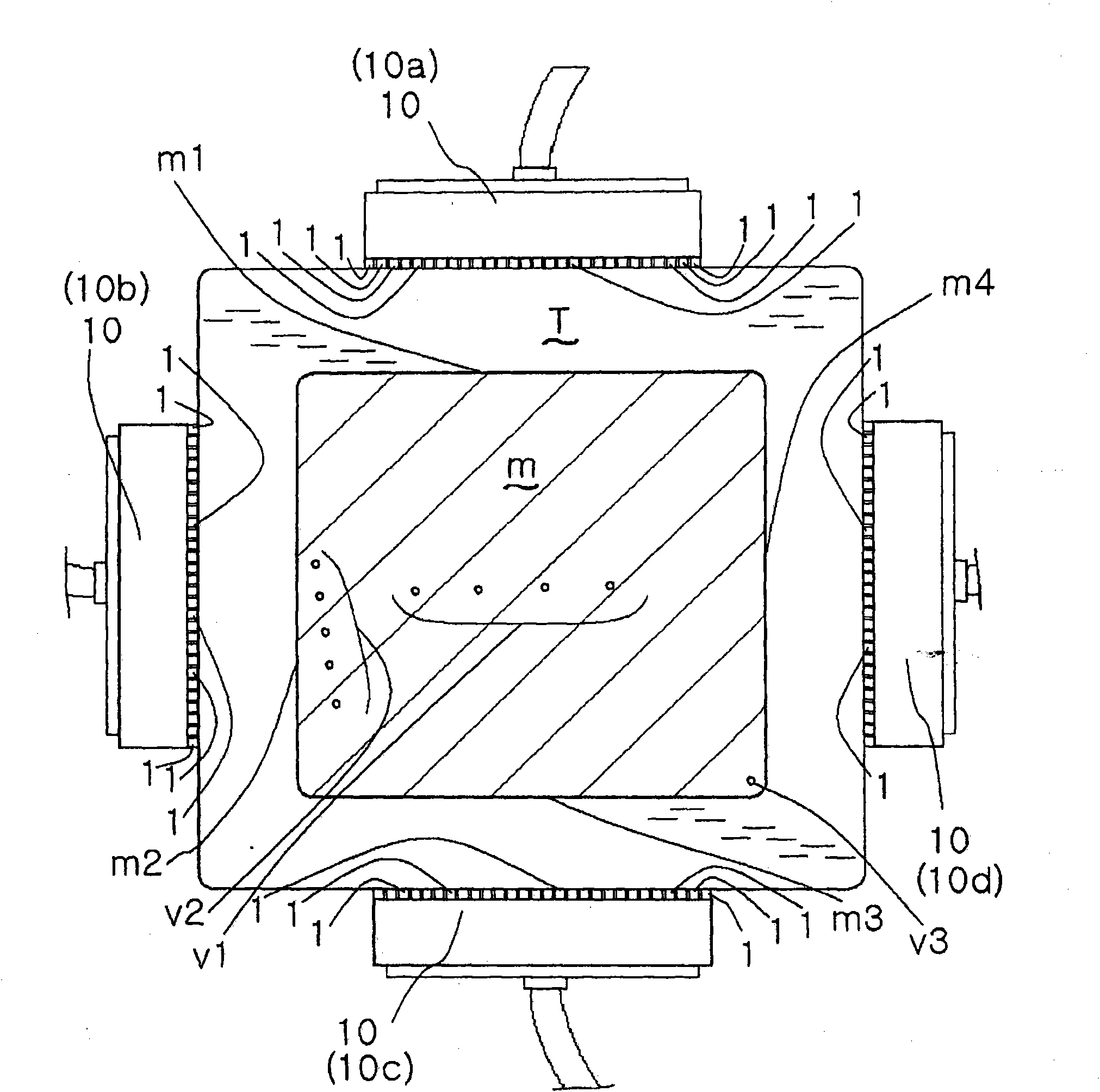
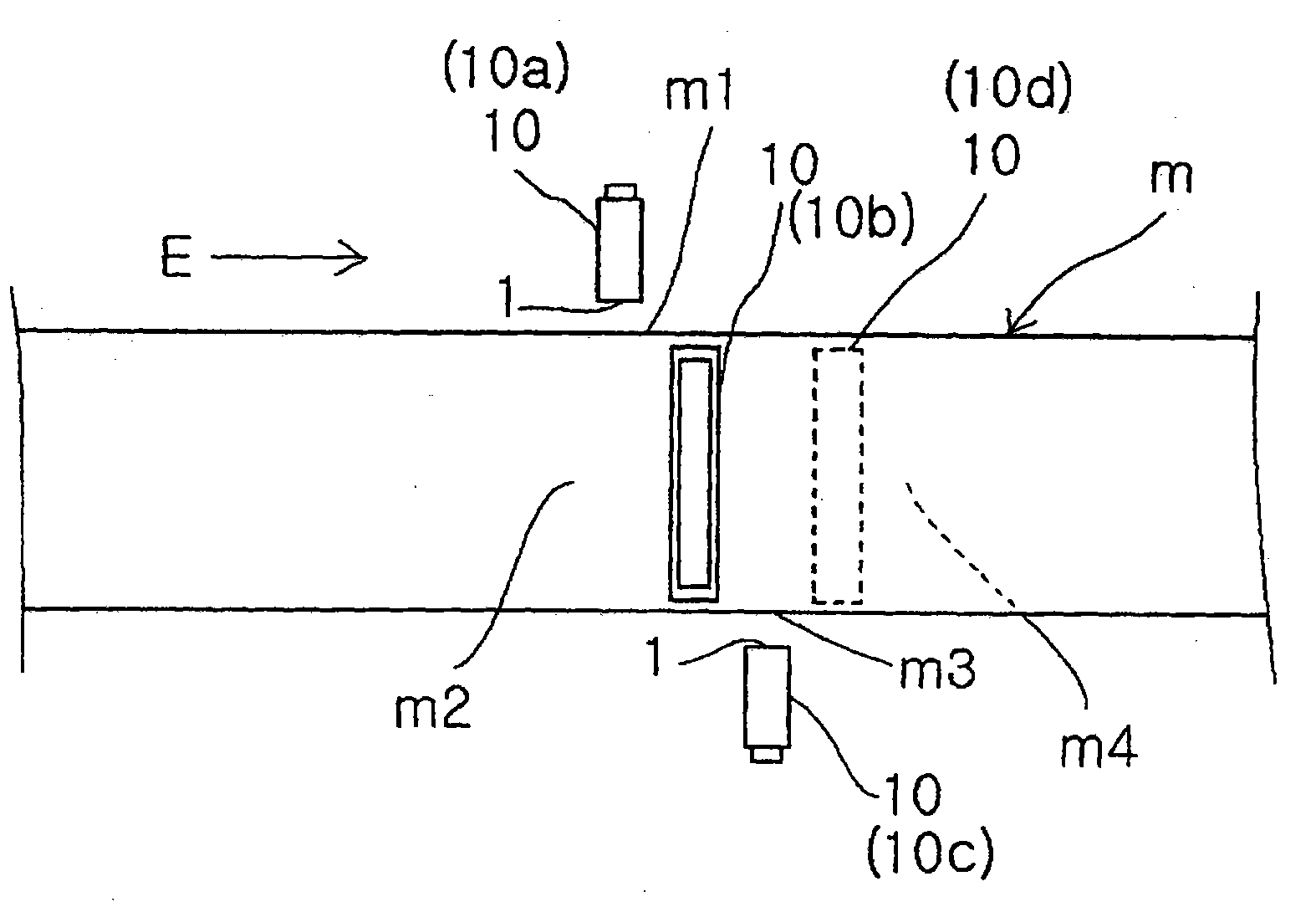
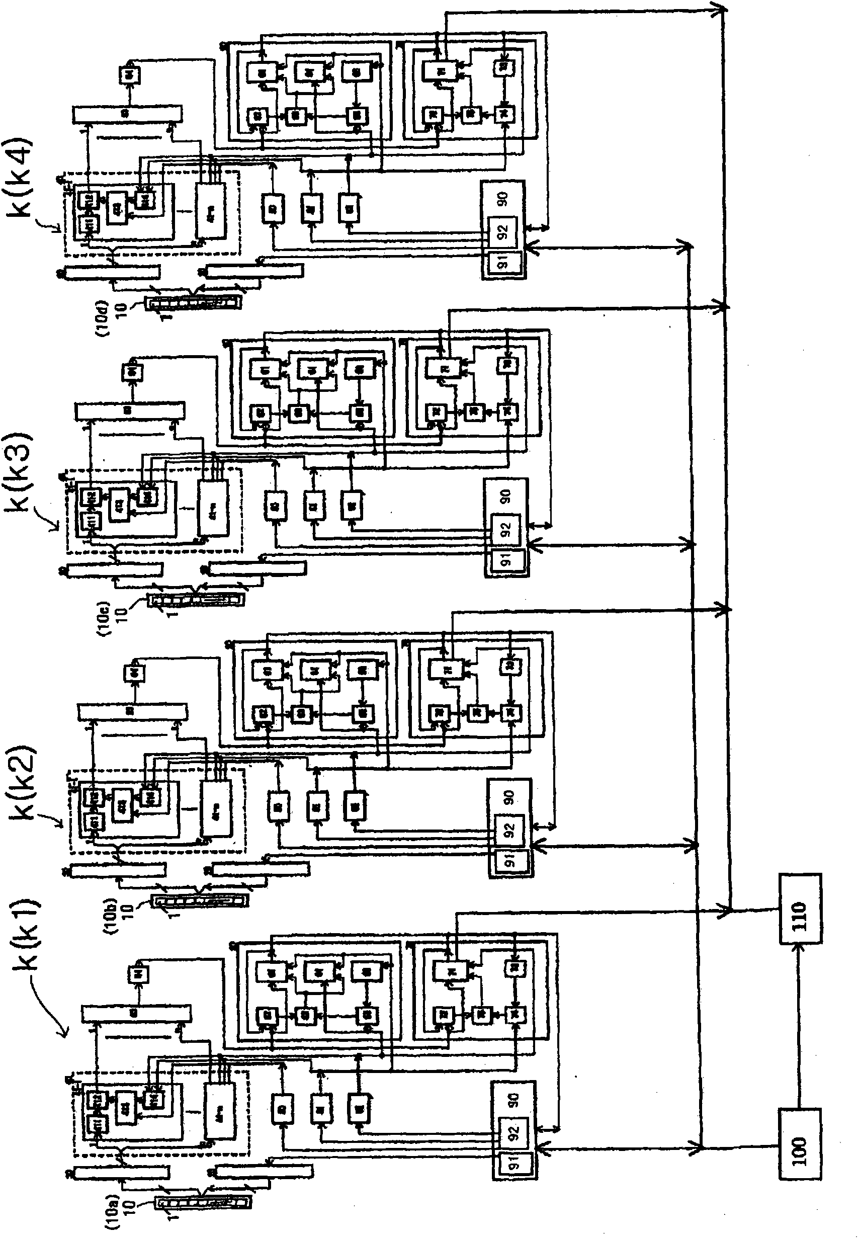
[0096] figure 1 It is a schematic cross-sectional view showing the arrangement of an array probe of a device according to an embodiment of the present invention. figure 2 It is a schematic side view showing the above arrangement. image 3 is the block diagram of the device. Figure 4 is enlarged image 3 The block diagram of the main part of the block diagram. Figure 5 It is a schematic cross-sectional view showing a state in which one array probe of the above device transmits ultrasonic waves to a test material. Figure 6 It is an explanatory drawing about the oblique flaw detection of the above-mentioned device. Figure 7 It is a flowchart showing the control procedure of the above-mentioned ultrasonic flaw detection device. Figure 8 It is an explanatory diagram showing a virtual elec...


PUM


Abstract

A device of the invention uses the volume-focus flaw detection method. Transducers (1, ..., 1) of an array probe (10) are arranged along one side of a rectangle of the cross section of an object (m) under test, and those (1, ..., 1) of another array probe are arranged along another side adjacent to the one side. Exciting means allows the array probes to direct ultrasonic waves to the corresponding incident sides along which the arrays are arranged, to cause the ultrasonic waves to enter the inside of the object through the corresponding positions of the incident sides by vibrating the transducers once by vertical flaw detection and oblique flaw detection respectively, to cause the ultrasonic waves which have been made to enter the inside by the vertical flaw detection to reach the opposite side to the incidents side, and to cause the ultrasonic waves which have been made to enter the inside by the oblique flaw detection to reach a side adjacent to the incident side. No real focuses of the ultrasonic waves are set inside the object under test.

Description

technical field [0001] The invention relates to an ultrasonic flaw detection method and a device thereof. Background technique [0002] Patent Document 1: Japanese Patent Laid-Open No. 2003-130859 [0003] Patent Document 2: Japanese Patent No. 3704065 [0004] Non-Patent Document 1: Murakami Joko, Dominic Burakonie, Miura Shunji, Murai Junichi, Nishitani Toyo: The 13th Ultrasonic Wave Niyoru Non-Break Review Lecture Collection of Lectures, pp.33-38, (2006) [0005] Non-Patent Document 2: Yokono Yasukazu: Current Status of Standardization of Feizudarei UT, NDI Document 21776, pp.34-38 (2006) [0006] Non-Patent Document 3: Masashi Mizuno, Hisao Nakase, Hiroshi Kota; Non-Patent Research, 37(11), pp.861-868, (1988) [0007] Non-Patent Document 4: Edited by the Subcommittee of Non-Cracked Inspection of the Quality Management Division of the Japan Iron and Steel Association Joint Research Society: Ultrasonic Flaw Detection Method for Bar Steel, pp.79, (1993) [0008] In the ...

Claims


Application Information

Patent Timeline
Patent Type & Authority Applications(China)
IPC IPC(8): G01N29/04G01N29/24G01N29/26
CPCG01N29/4454G01N29/262G01N29/221G01N29/043G01N2291/106
Inventor 村井纯一D·布拉科尼耶
Owner NIPPON KURAUTO KUREEMAA FUERUSUTAA
Learn More