
Apparatus for joining a carcass ply

A carcass ply and equipment technology, applied in tires, applications, household appliances, etc., can solve the problems of difficult to maintain precision, difficult production, complex structure, etc., and achieve the effect of simplifying the cylinder

Inactive Publication Date: 2010-08-25
MITSUBISHI HEAVY IND LTD
View PDF3 Cites 3 Cited by
  • Summary
  • Abstract
  • Description
  • Claims
  • Application Information

AI Technical Summary

Problems solved by technology

The structure in which the cylinder part (block) is set radially inwardly retracted in the cylinder may

Method used


Image

  • Apparatus for joining a carcass ply
  • Apparatus for joining a carcass ply
  • Apparatus for joining a carcass ply

Examples


Embodiment 1

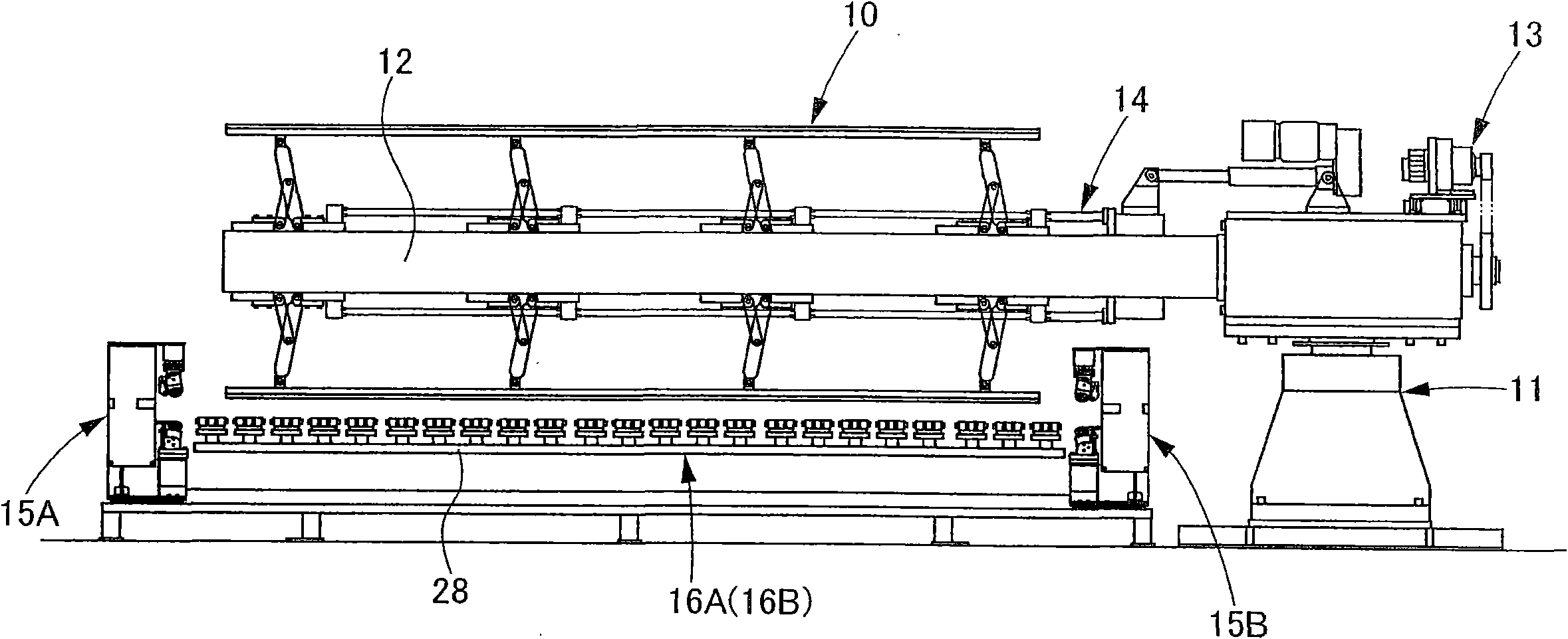
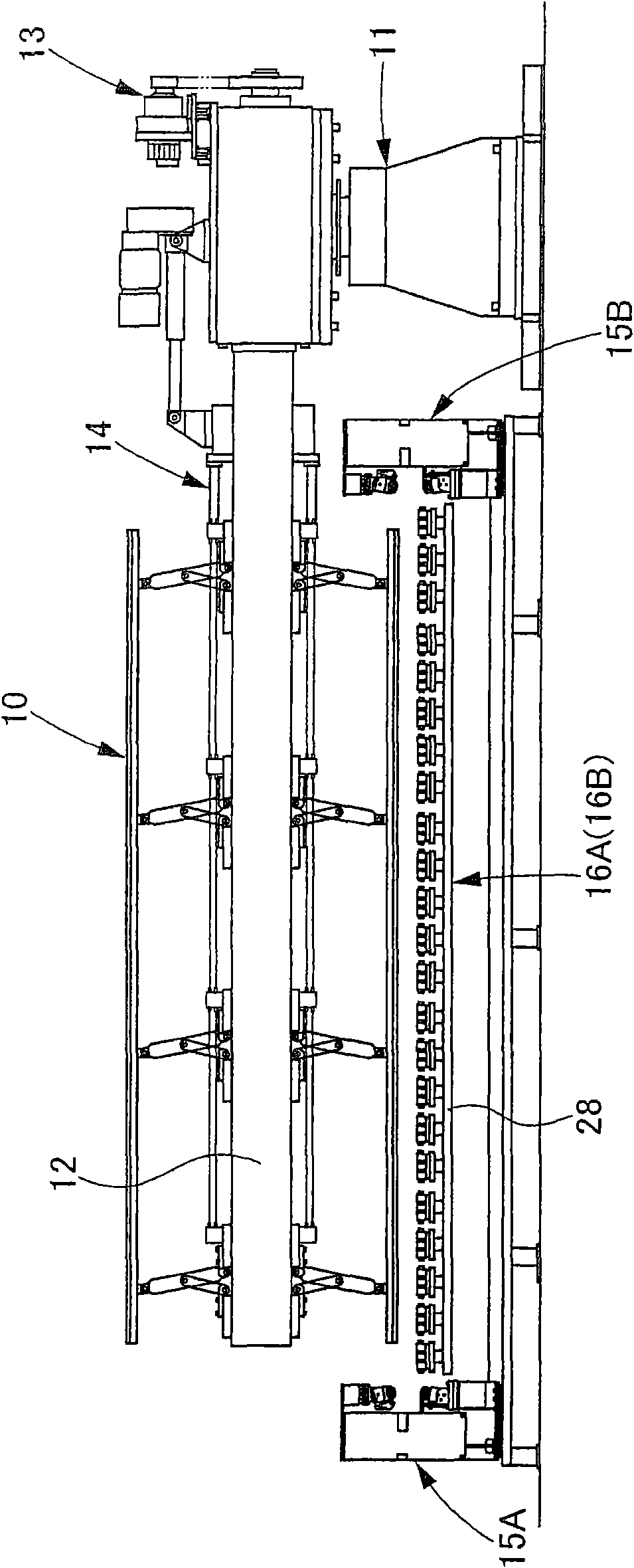
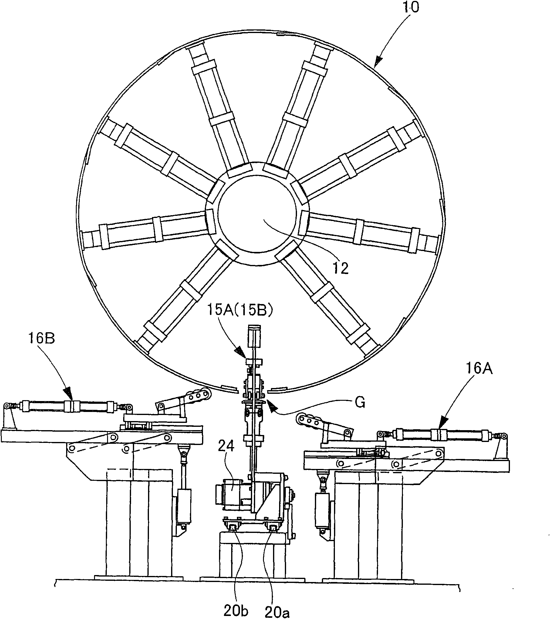
[0042] Fig. 1 is a front view showing an apparatus for joining carcass plies according to Embodiment 1 of the present invention. Figure 2 is a side view of an apparatus for joining carcass plies. Fig. 3 is a front view of a connection part. Fig. 4 is a side view of the connecting portion. Fig. 5 is a detailed side view of the alignment part. Fig. 6 is an explanatory view of the movement of the cylindrical barrel. Fig. 7 is another movement explanatory diagram of the cylindrical barrel. FIG. 8 is a detailed view of FIG. 7 . Fig. 9 is an explanatory diagram of the movement of the connecting portion. Fig. 10 is an explanatory diagram of movement of registration rollers. FIG. 11 is a detailed view of FIG. 10 . FIG. 12 is an explanatory diagram of movement of the alignment unit. Fig. 13 is an explanatory diagram of the movement of the connecting roller and the alignment roller. FIG. 14 is a detailed view of FIG. 13 . Fig. 15 is an explanatory diagram of movement of the al...


PUM


Abstract

The invention discloses an apparatus for joining a carcass ply, which butt-joins a wind start end and a wind finish end of a carcass ply wound around a cylindrical drum, is disclosed. The apparatus comprises: a joining section for joining the ends of the carcass ply; and aligning sections for aligning the ends of the carcass ply during joining by the joining section, the joining section and the aligning sections being disposed below the cylindrical drum supported in a horizontal state.

Description

technical field [0001] The present invention relates to an apparatus for joining carcass plies used in the tire manufacturing process as a material constituting the tire. Background technique [0002] With this type of equipment, the carcass ply is formed by winding a sheet material cut to the size of one tire around a cylindrical cylinder and butting the connecting ends (winding start end and winding end end) of the sheet material. Formed as a strip-shaped part. In order to ensure the strength of the joint formed by butting, it is necessary to set conical connecting rollers (toe-in roller device) on both surfaces of the carcass ply, and generate strong force from both sides of the connecting line (connecting line or joint line) extrusion force. [0003] To achieve the above object, for example, Patent Document 1 discloses a structure in which an end portion (hereinafter referred to as a connection end) for supporting a carcass ply to be connected of a cylindrical portion ...

Claims


Application Information

Patent Timeline
IPC IPC(8): B29D30/30
CPCB29C65/7802B29C65/56B29C65/785B29C66/1142B29D2030/422B29D30/42B29C66/4322B29C66/8362B29C65/7855B29C66/221B29L2030/004B29D30/24B29D30/30B29C66/49B29C66/81419B29C66/81469Y10T156/1715B29D30/20B29D30/26
Inventor 橘诚宫本义则
Owner MITSUBISHI HEAVY IND LTD
Learn More