Rail expansion device

A telescopic device and rail technology, applied in the direction of rails, roads, rail joints, etc., can solve the problems that wear-resistant steel cannot be used, difficult to weld, etc., and achieve the effects of reliable guidance, simple structure, and easy maintenance.

Active Publication Date: 2010-08-25
VOESTALPINE BWG GMBH & CO KG +1
View PDF5 Cites 2 Cited by
  • Summary
  • Abstract
  • Description
  • Claims
  • Application Information

AI Technical Summary

Problems solved by technology

Moreover, not all materials can be welded to each other, which exposes the disadvantage that wear-resistant steels that are difficult to weld cannot be used for this reason

Method used


Image

  • Rail expansion device
  • Rail expansion device
  • Rail expansion device

Examples


Embodiment Construction

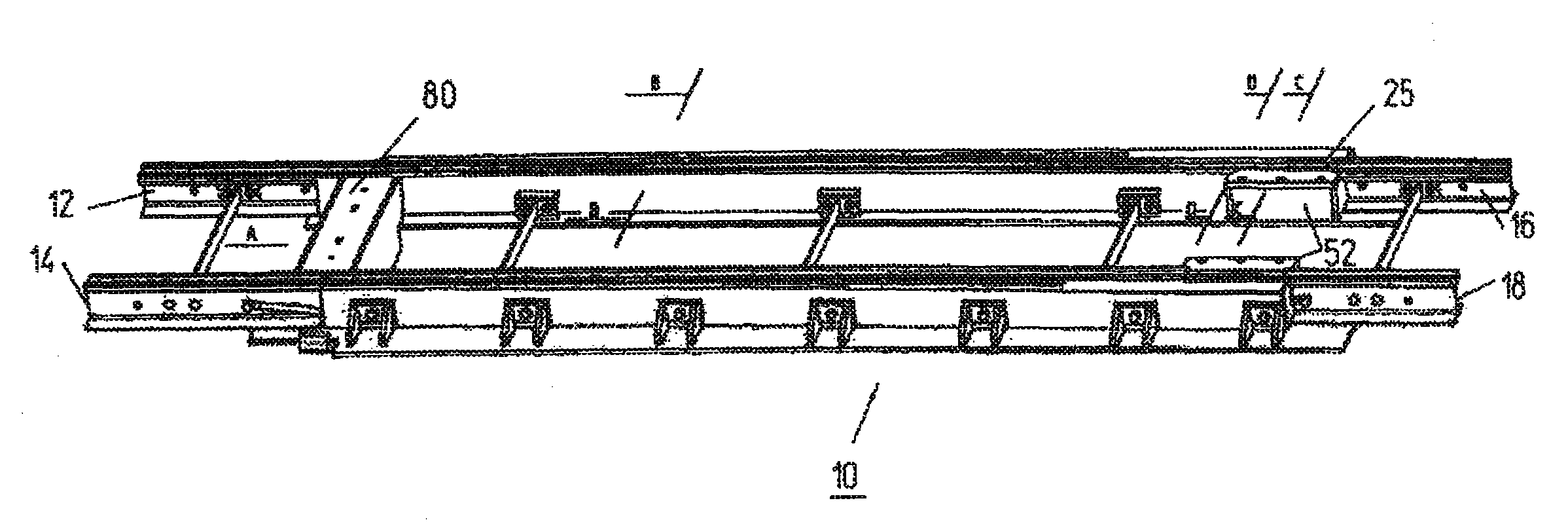
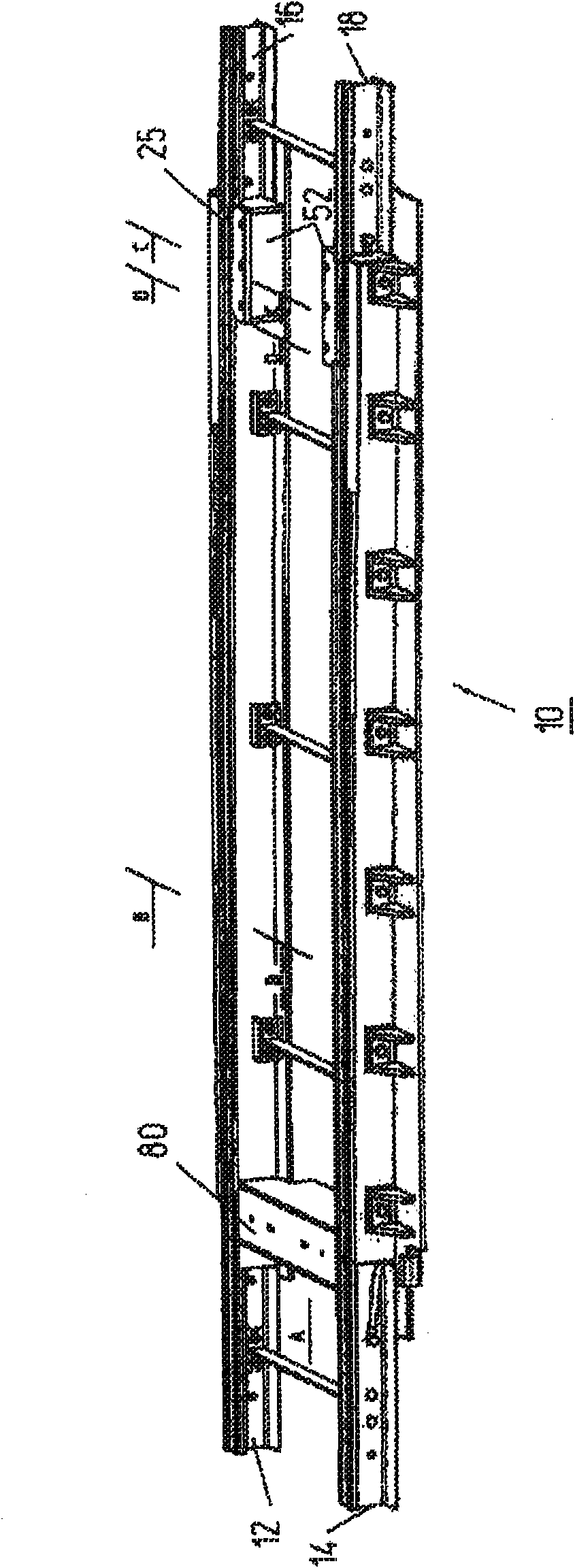
[0025] A purely principled rail telescopic device 10 is shown in the drawing, which is a grooved rail, without thereby restricting the principle according to the invention. Conversely, this arrangement is also suitable for other rail sections, in particular T-shaped rails.

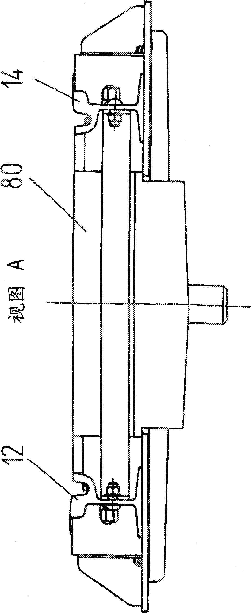
[0026] The track telescoping device 10 generally comprises base rails 12, 14 which are longitudinally displaceable relative to a tip rail 21 which transitions into the control rails 16, 18, the tip portions 20 of which are shown in the views of FIGS. 3 and 4 and a cross-sectional view of the root region 22 . In order to be able to move relative to the current temperature between the base rails 12, 14 and the switch rails 21 transitioning to the control rails 16, 18, the base rails 12, 14 leave the switch rails 21 outwards, so that regardless of the active position of the base rails 12, 14 Regardless of the length, there is always a transition from the tip rail 21 or its tip 20 to the base rail 12 , 14 . ...


PUM


Abstract

Rail expansion device (10) having stock and tongue rails (12) which can be displaced longitudinally with respect to one another and bear against one another transversely with respect to the longitudinal direction of the rails under the application of force, wherein a holder releasably holds the tongue rail at a distance from the region thereof which bears against the stock rail (12), and wherein the tongue rail in the holder is non-positively and positively connected to a standard rail (16, 18) passing into it or to a section thereof or to a section of the holder whose profile merges with that of the standard rail.

Description

technical field [0001] The invention relates to a track telescopic device, which has a base rail and a switch rail which can move relative to the longitudinal direction and exert force on each other transversely to the longitudinal direction of the track. Background technique [0002] Rail telescoping devices, also called expansion joints, are installed, for example, in bridging areas in order to enable relative movement between the building and the rails. In this case, the switch rail is basically arranged to be movable relative to the base rail. For this purpose, for example, the switch rail can be arranged between the base rail and the clamping pieces arranged fixedly on the opposite side. The switch rail foot and the base rail foot then proceed from a common base plate, as described for example in DE-A-1 534 052 . [0003] In the rail telescoping device according to WO-A-93 / 23624, the base rail can be arranged displaceably relative to the switch rail, wherein the switc...

Claims


Application Information

Patent Timeline
Patent Type & Authority Applications(China)
IPC IPC(8): E01B7/02E01B11/42
CPCE01B11/42E01B7/02E01B2/003E01B11/24E01B11/56E01D19/12
Inventor T·克里斯特T·伯格克
Owner VOESTALPINE BWG GMBH & CO KG
Why Eureka
Try Eureka