Antenna having a choke member
A technology for components and antennas, which is applied to antennas, individually powered antenna arrays, antenna arrays, etc., and can solve problems such as passive intermodulation distortion of antennas
Inactive Publication Date: 2010-08-25
ACE TECH
View PDF0 Cites 5 Cited by
- Summary
- Abstract
- Description
- Claims
- Application Information
AI Technical Summary
Problems solved by technology
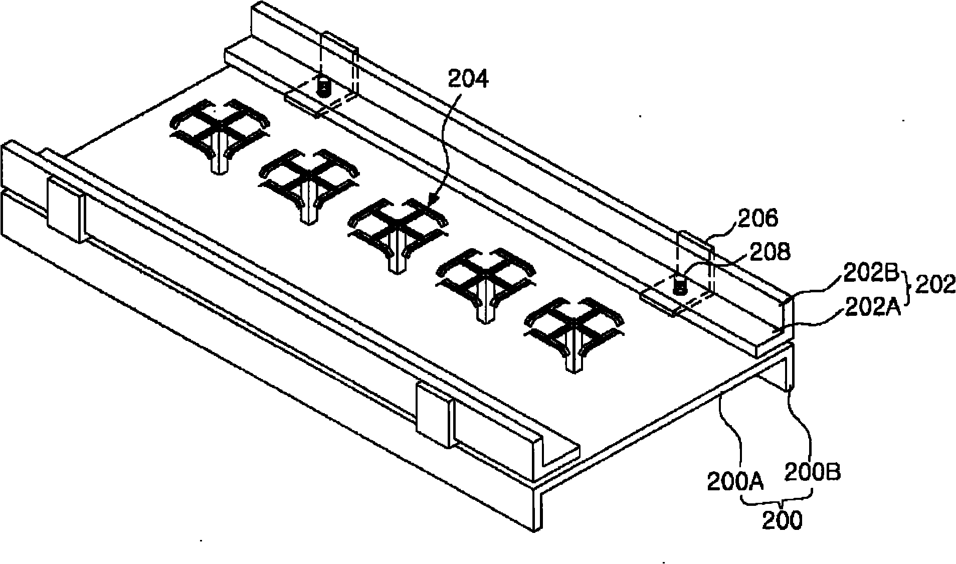
In this case, a choke member made of metal is directly formed on the reflection plate 100, and as a result, severe passive intermodulation distortion (hereinafter, referred to as "PIMD") occurs in the antenna.
Method used
View moreImage
Smart ImageViewing Examples


Examples
Embodiment Construction
Login to View More PUM
 Abstract
An antenna for enhancing characteristic of a beam with reducing PIMD is disclosed. The antenna includes a reflection plate, at least one first choke member disposed on one side of the reflection plate, an insulated member disposed between the reflection plate and the first choke member, thereby separating the first choke member from the reflection plate, wherein the insulated member is an insulator, and a connection member configured to connect electrically the first choke member to the reflection plate through the insulated member, wherein the connection member is a conductor.
Description
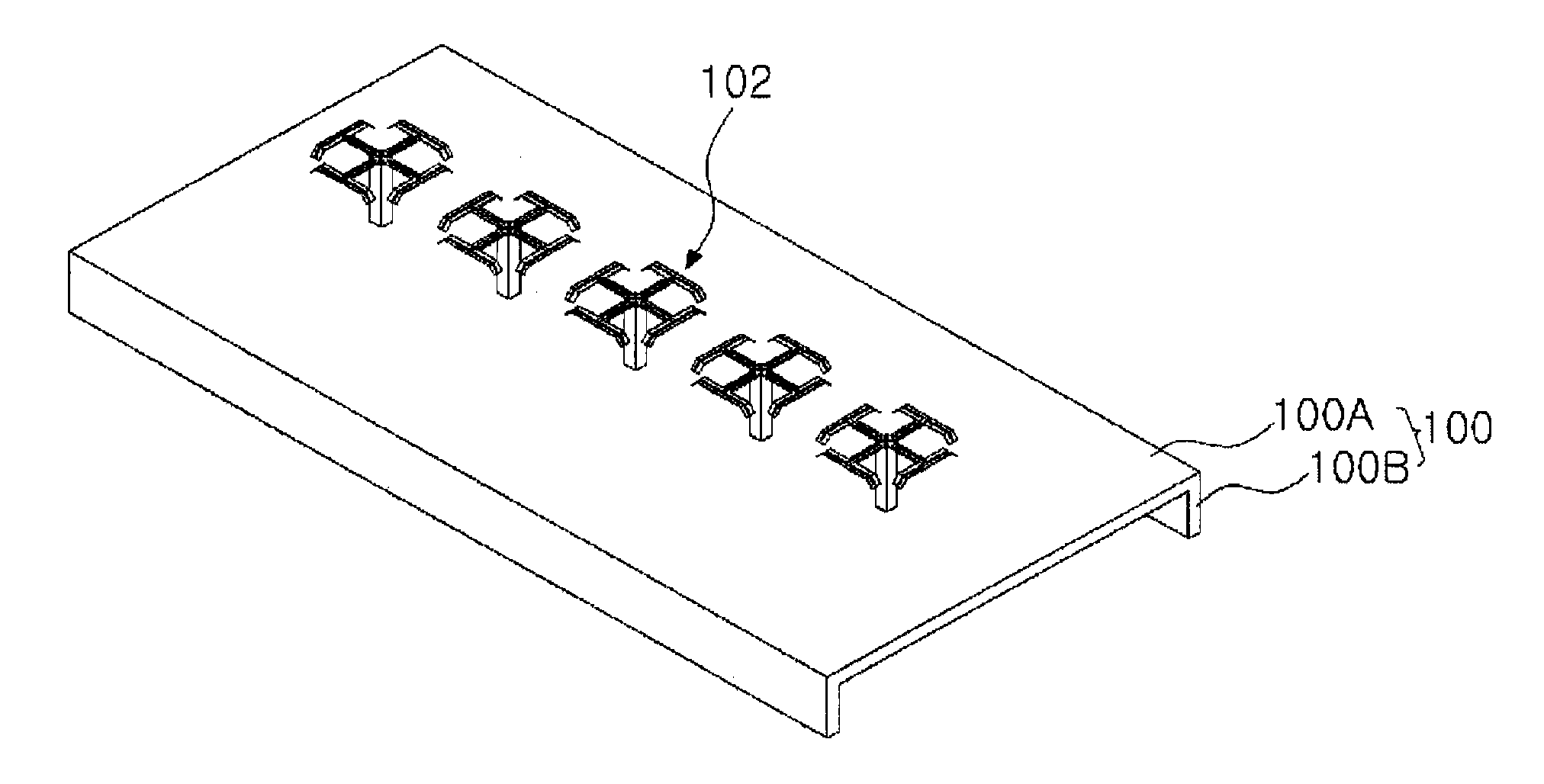
technical field Exemplary embodiments of the present invention relate to an antenna having a choke member, and more particularly, to a PIMD-reduced antenna connecting a choke member to a reflection plate. Background technique The antenna transmits / receives electromagnetic waves by radiating a radiation pattern, and generally has the following structure shown in FIG. 1 . FIG. 1 is a perspective view showing a general antenna. In FIG. 1 , the antenna includes a reflector 100 and a radiation device 102 . The reflection plate 100 has a shape bent in a certain direction as shown in FIG. 1 , and includes a base member 100A and a bending member 100B. The radiation devices 102 are sequentially arranged on the reflection plate 100 . The antenna outputs a beam in a given direction using a radiation pattern radiated from the radiation device 102 . A phase shifter (not shown) is formed on a second surface opposite to the first surface of the reflection plate 100 on which the r...
Claims
Login to View More Application Information
Patent Timeline
 IPC IPC(8): H01Q21/00
CPCH01Q21/08H01Q19/021H01Q19/106H01Q21/26H01Q1/24H01Q3/26H01Q21/00
Inventor 慎弼守吴秉一
Owner ACE TECH